
In my last post, I described the beginnings of a LEGO Classic Space Next Generation Command & Control Center Module.
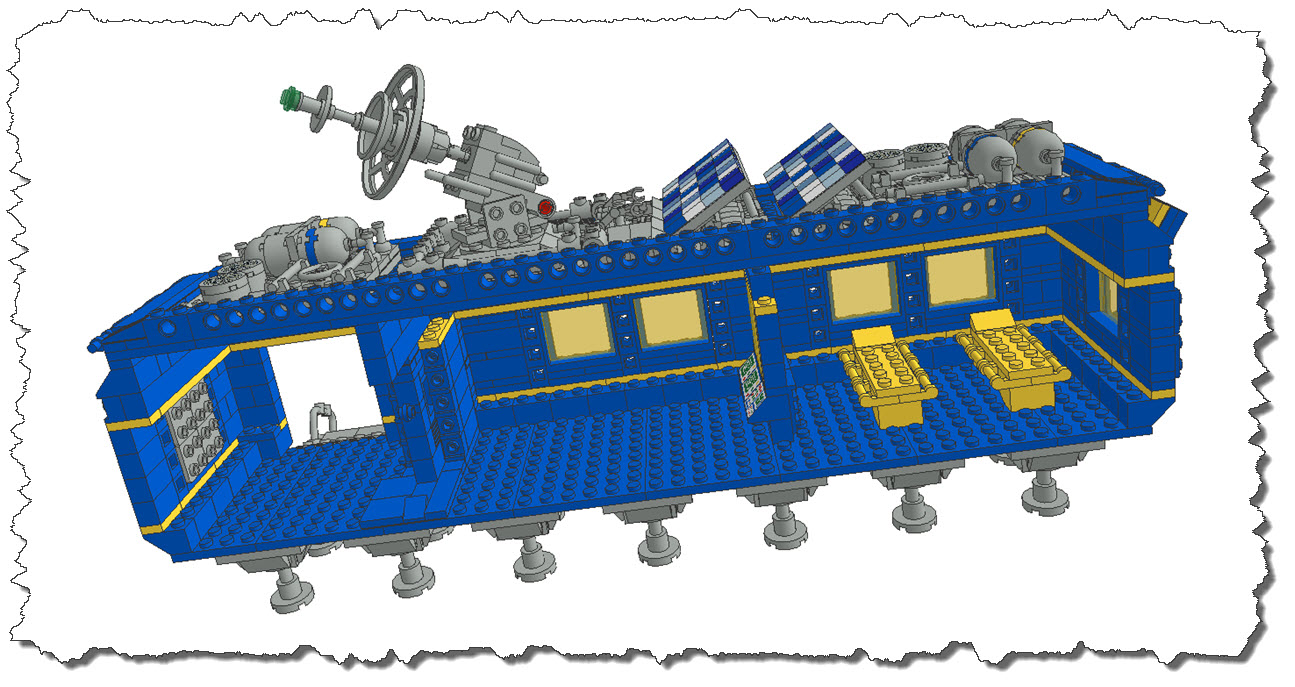
I have now finalized that portion of the set and completed the root structure, adding some Solar Panel with Extension and another Pressurizer Unit for the main section of the module.
 The Interior Parts
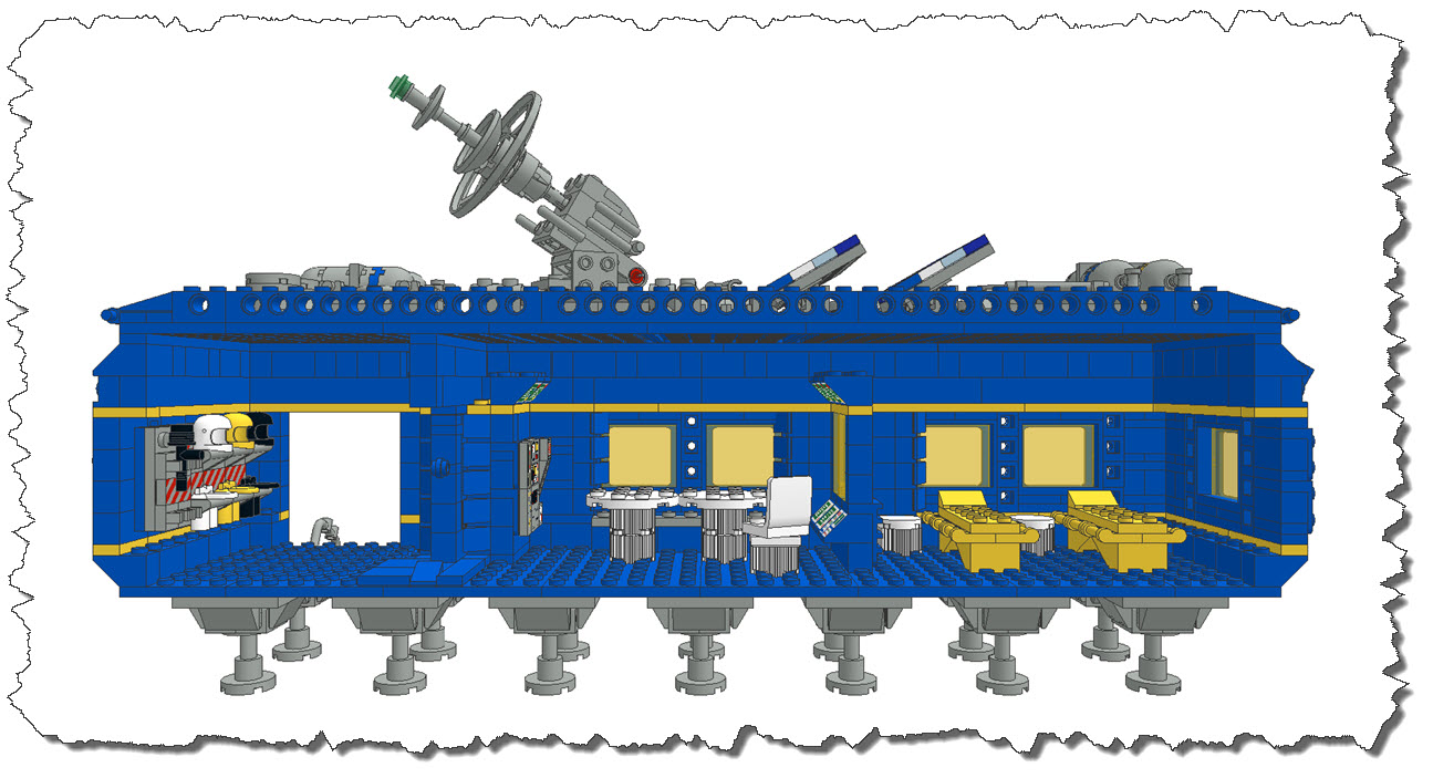
Now, with the outer walls and roof finished, it is time to think about a modular approach to the interior part. The challenge are the wall section – typically, the Classic Space sets featured little to nothing on the interior side – slope bricks with computer displays and specific larger wall bricks such as Part ID 3754, a Brick 1 x 6 x 5 with two printed motives were the maximum there was. These days, there are many more bricks one can use to create a more “dedicated” interior for different modules. Especially, the 1 x 2 and 2 x 2 Tiles with different designs make up nice computer walls. Slope bricks are still around and then of course you may want to mount one or the other clip brick to hold equipment.
Wolf Leews used the outer walls with angular plates in his LEGO Idea “LL928 Comes Home”. I have added a sample of this approach in my airlock section where you can see the gray brackets providing studs for vertical mountings in the image above. While is approach works very well, it still does not provide me with the flexibility and modularization I would like to have. So instead, I am going to utilize the “step” that is left at the bottom of the module when switching from the 2 x 2 inverted slope bricks to the 1 stud-wide walls as an anchor point. If course, this will make the windows a bit “deep” but I am going to break this up as you will see.
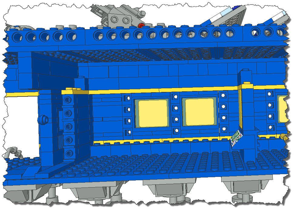 The wall along the airlock door towards the wall is 4 studs at the floor level and 5 above the slope brick. Also, from the airlock door to the window, we are dealing with 4 studs. The area underneath the ceiling provides enough space to proper anchoring of the structure to make it stable.
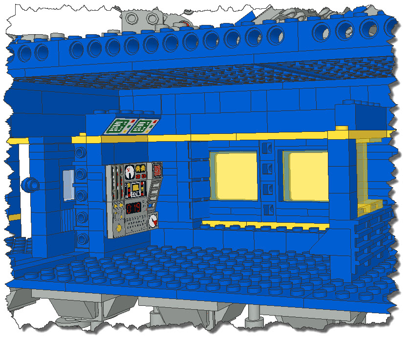
 One example for a technical corner section is displayed on the left. The exact way to build it (when physically built) will be more or less determined by the types of tiles you can get – those with technical displays also fit for a Space Station can be pretty rare…
But I think, you can get the idea. Again, the panels are mounted on brackets build into the support structure in the back. In my case, I have mounted them on a 4 x 4 plate but that make the display rather “thick” – if you want it thinner, you can place the tiles directly on the brackets, no problem. Also, it remains taste if you want to angle off the window section – if you don’t, you can remove the 1 x 1 bricks I used for the mounting of the small slopes and build the wall in a regular way. That would then provide space for more brackets, e.g. LEGO ID 42446 (a 1 x 1 bracket). That way, you would be able to mount additional 1 x 2 tiles vertically and add more technical displays.
 We did say that this was a module to serve as a kind of “ready room” for the Command Center itself – we got our sleeping area, now our space men should also have some sort of “hang-out area” to read the odd book or watch an occasional movie (I assume, they will be using their tablet computers for that, so there will be no monitors on the wall or book-shelfs required). But what we need is some seating and maybe a table or two to place stuff and put those drinks (non-alcoholic, we are “on duty”!) down.
The seating is easy – I will reuse the line of studs left beneath the window section and just make it a bit wider.
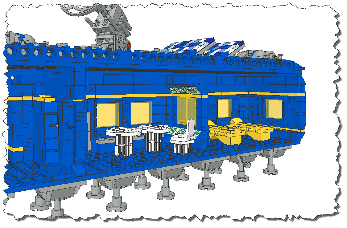 With a bit of seating, the completed separator wall, a few more monitors under the ceiling and two tables, th crew area is finished. Well – almost: the last step here is the connection of the structures to the roof plates (which is really just building them up vertically).
Last but not least, the airlock has received an equipment holder – it will not quite work when physically built: the air tanks will needs a support structure below to actually remain in their lots – but otherwise, things work.
 I finally rendered the model though POVRay rather than working with the faster but cruder LDView Rendering.
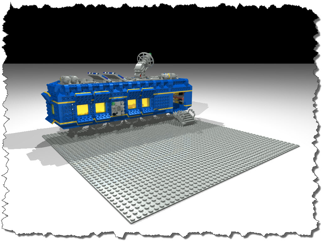 As you can see, I already mounted the module on a 50 x 50 base plate to prepare for the outside elements – some antennas, maybe a generator block, etc. Also, the inside has received a high-resolution rendering.
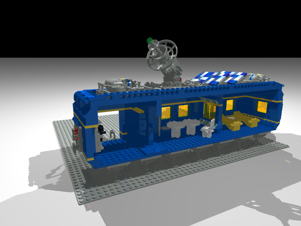 Nice view of the solar panels and other roof elements as well… so much for now, I will have to complete the interior one of these days (building it all up to the ceiling), then attach the outside elements of the module and some external items as mentioned before. But that will be another day…