Some time back, I posted an article on the ZX81 Computer I got off eBay and how coding of old listing was done way back when.
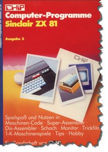 Now, that last article was dealing with a listing retrieved from an old CHIP Magazine, by now, I have gotten my hands on a second one and once more would like to bring one of these old listings “back to life”.
One thing I certainly don’t want to do though is to suffer through the same ordeal than thirty years ago: typing in those listing using the ZX81 Keyboard was tedious, slow and error-prone.
Using an emulator again, I could at least eliminate the frequent crashes and involuntary reboots of the true ZX81 when you – accidentially – touched one of the cables the wrong way. So what is out there to help?
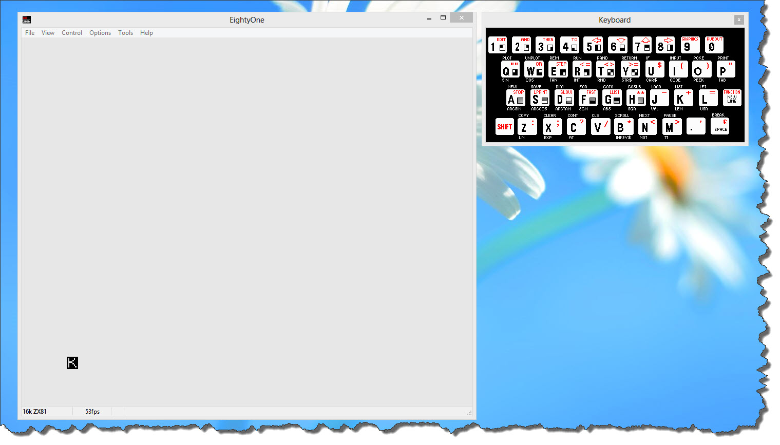
EightyOne – the Emulator of choice (still!)
First of all, of course, the emulator itself. I still stick to EightyOne (available here) as the emulator of choice. Although released in 2006, it runs perfectly stable, even in my Windows 8 environment.
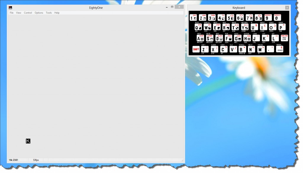
One thing, however, it cannot do: it cannot accept a cut & paste of text to bring in those BASIC Listings. So if I would just look for a stable environment and then type the listings in myself, I would be well served. But that ain’t no good.
Coding outside the Emulator Environment
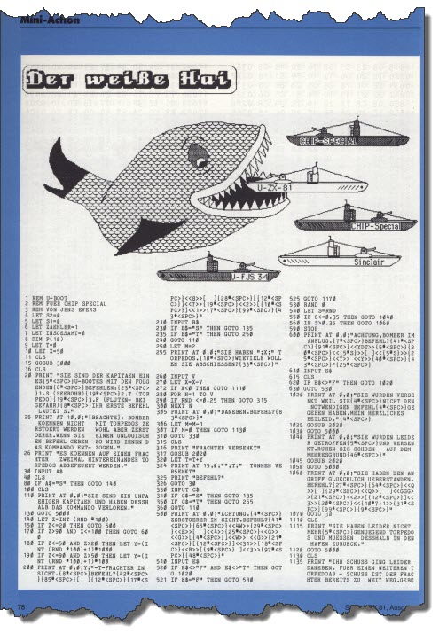
 I have randomly picked a listing from the CHIP Magazine, and I have no intentions to type it in the ZX81 emulator.
Wouldn’t it be nice if I could just type the code into a modern text editor, probably use features like syntax highlighting and cut & paste and any of the cool features modern source code editors have?
I could also use existing tools such as Subversion for revision control, etc.
So let’s give it a try – the editor of choice is Notepad++, which – if you have not seen it yet – is certainly something you should have a look at. You can find it here and trust me: it is by far the best editor (personal gusto) that you can have when it comes to a generic text file editor.
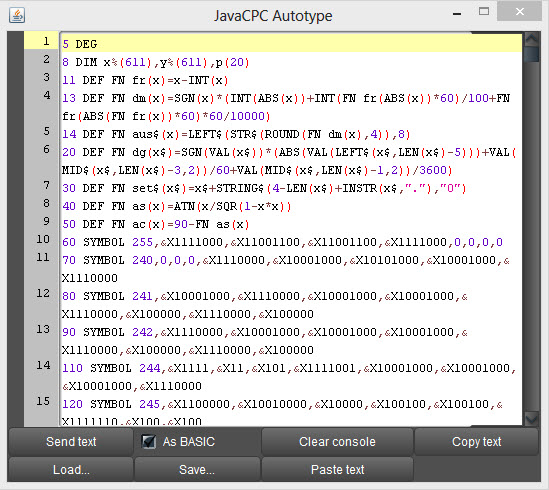
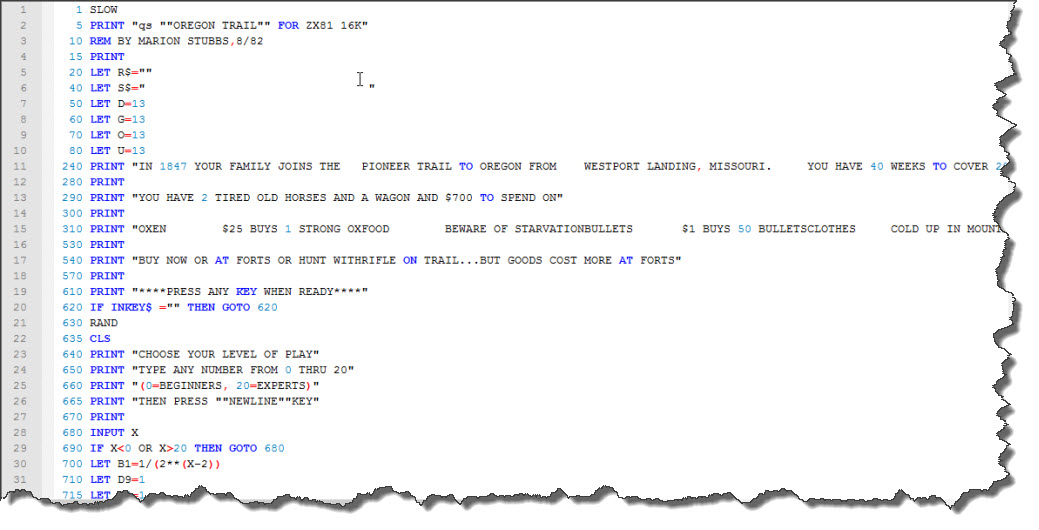
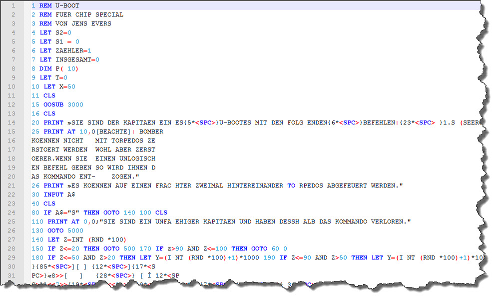
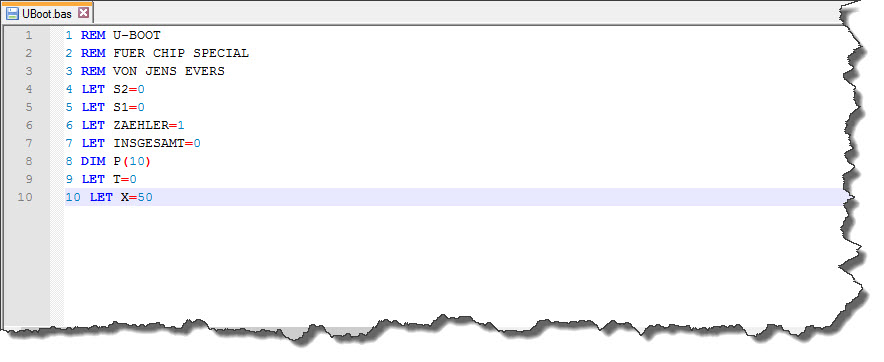 So here are the first few lines of code in Notepad++ – I have already stepped ahead a little bit and enabled syntax highlighting as well – I will show you later, how it was done.
Getting the ASCII Text into the Emulator
And just how do we get the listing into the emulator now? The answer is a little tool called TXText2P – a command-line utility that can convert a text file into a P-File that can then be loaded by the ZX81 Emulator. In my case, the listing was saved to a file called uboot.bas so my command line is
zxtext2p -o uboot.p uboot.bas
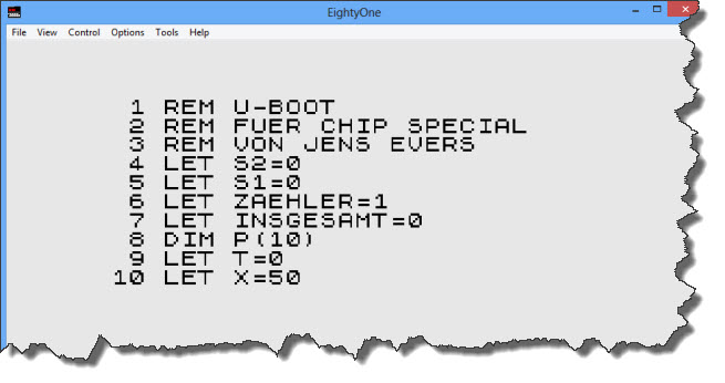
And that is all… in EightyOne, the file can now be loaded by File > Open Tape… and selecting the resulting uboot.p file.
 So I am half way there – I can code and control from outside the ZX81 emulator, then bring the listings into the ZX81 environment and run them there.
On a side node, I would like to mention the Retro Isle website from where I was able to retrieve a copy of ZXText2P – thanks guys for the site and the download!
Avoid Typing altogether
At the end of the day, programmers are lazy – which is probably why they have become programmers: if you can simplify or automate a task, we can do it. And typing listings into text editors is certainly something to automate!
The tool of choice here – for me at least – is ABBEY FineReader. FineReader is an OCR Program that allows to manipulate the recognition engine in many ways.
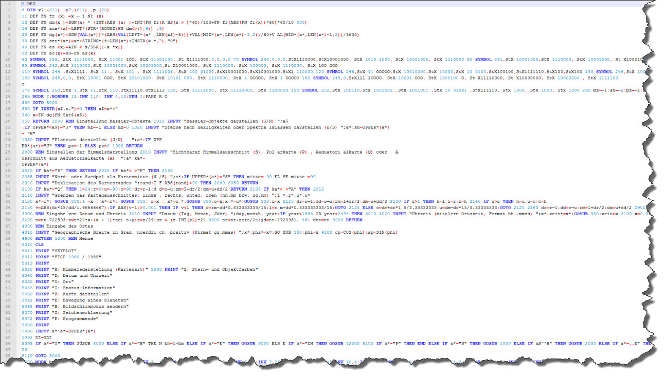
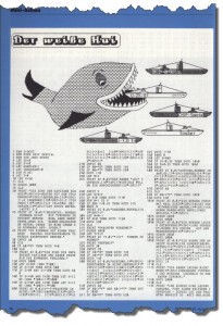
In the case of my listing, I have two scanned pages with the listing itself – so I pull my two scans into FineReader for processing.
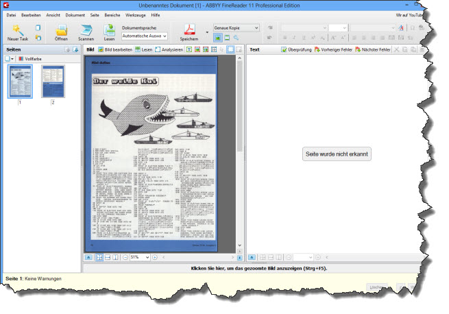 In the next step, I tell FineReader where the interesting text is and how I want it processed. I could automate this but given that there are only two pages, I go the “manual way”. Then, I ask FineReader to “read” the text areas.
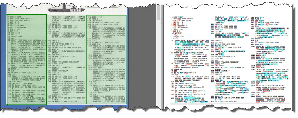 The easiest way to get the text into Notepad++ is to simply save it as Text File, then rename it to a BAS-File (just for organization) and then open it in Notepad++.
Cleaning up the OCR Result
A comment first: when code was lost in the old days, it was mostly due to the computer (especially the ZX 81) giving in to the circumstances (in this case: an involuntary restart because of a brief loss of power). These days, the loss of code (especially with lots of re-working) is more on unvoluntary overwrites – so storing the result in some sort of source code control system (e.g. Subversion) is a good idea.
First Round of Cleaning
A first look at the OCR Result can be disappointing – but consider this: it is probably easier to clean the code up than to type it from scartch, especially since many clean-up steps can be done via search & replace.
 First of all: just how yo do the clean-up is entirely up to you. I will go through line by line, check the line visually, remove the blank lines and line-breaks and also some spaces within.
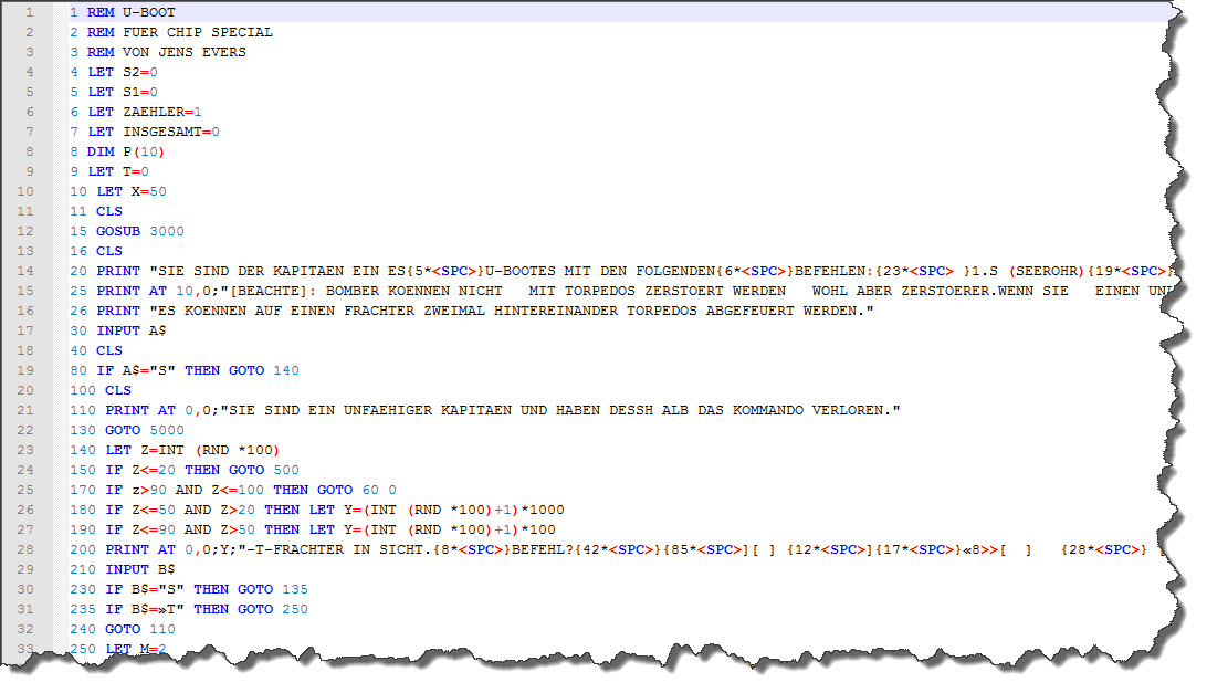
This hardly takes any time – after about 20 minutes or so, the BASIC listing is in a much better shape – each line has now been processed, blank lines have been removed and the first large errors have been eliminated. Now, fine-tunig is asked.
Line-by-Line Comparison
Next, is a line-by-line comparison of the code, which unfortunately cannot be avoided. Fortunately, I have a dual monitor environment so having the code on the one side and the listing (scanned) on the other makes it a bit easier.
The other thing to look at is the “built-in editing instructions” – you may have noticed the following line:
20 PRINT "SIE SIND DER KAPITAEN EIN ES{5*<SPC>}...
Noticed the Escape Sequence – {5*<SPC>}? This is no BASIC Code the ZX 81 would be able to interpret – this is an inline ediging instruction that simply says “place five spaces here”.
There are other such occurances – and they are a bit harder to come by: the ZX 81 featured “block graphics” characters – take a look at the keyboard:
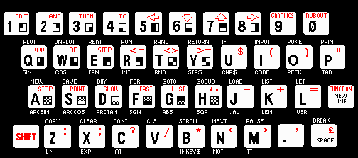
The block graphic symbols are on the lower right of many of the keys – if they would have been printed one to one in the listings (and some magazines did that) they had been a bit hard to distinguish from each other – so this magazine used more escape sequences to provide “help”:
2020 PRINT AT 4 ,0;"{10*<SPC>} <<G4>> <<1>>{25*<SPC>}...
Next to the already known ten spaces, the <<…>> escape sequence means “whenever you find something in between << and >>, insert the graphic symbol of the respective key” – this code is not only hard for the OCR to process – it is also extremly painful for the programmer to properly type in.
Enough talking – let’s continue to clean up the code. Another 40 Minutes later, all is done… time to run the program.
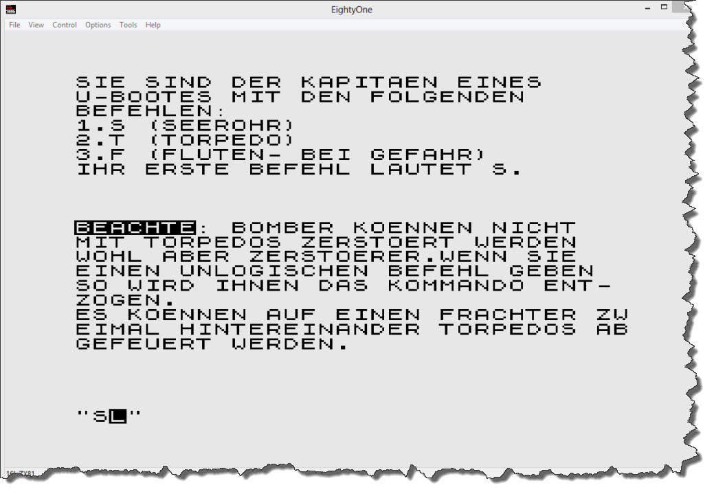
The first Start
Printed in 1985 and brought back to the emulator some 28 years later, it is not necessarily but possibly a very rare one out there. Running the program through ZXText2p and then loading it into the emulator is quickly done.
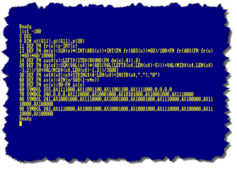
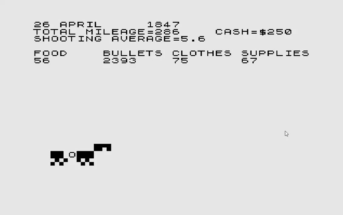
 Not too bad – looking for some example of those escape sequences resolved?
 As you can see, this is about the only thing that might have been easier in 1985 – you could directly see the outcome of the block graphics (if you factored in the “shift” caused by the preceeding command PRINT AT…) – Let’s run the program:
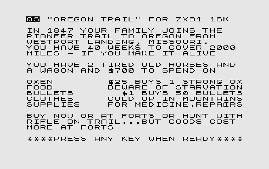
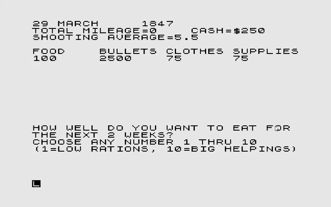
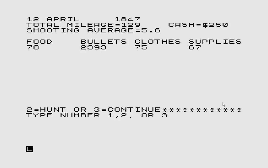
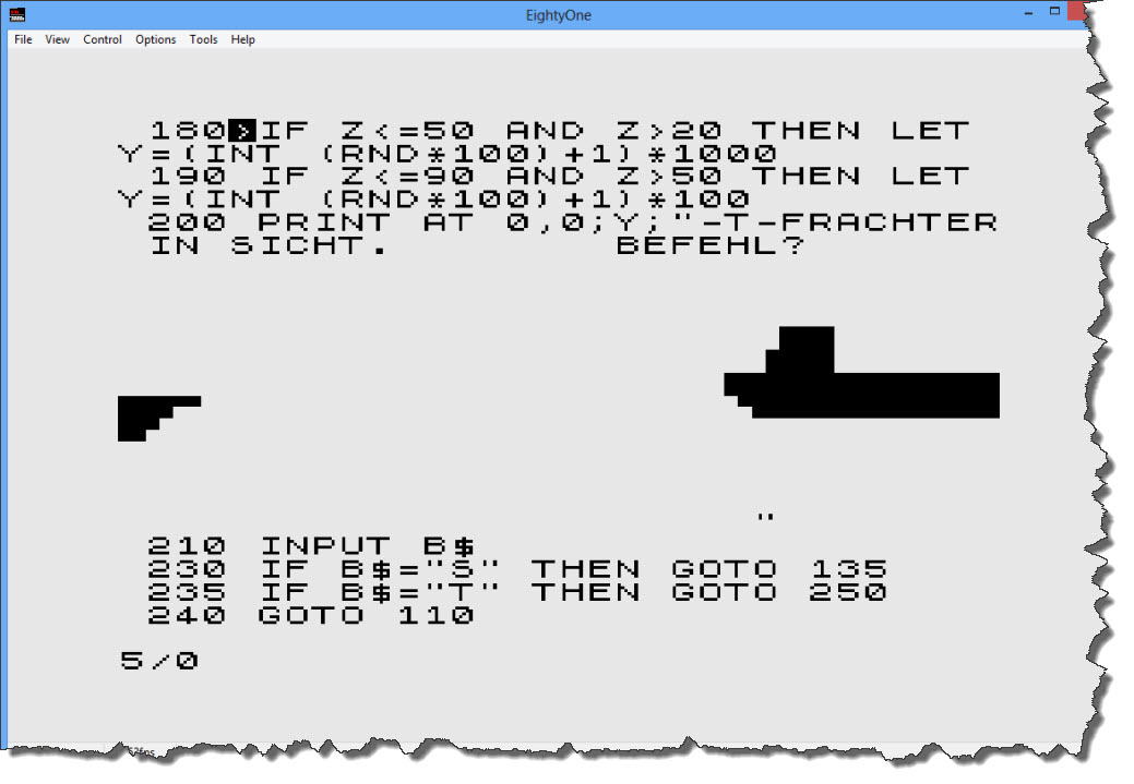
 After the opening screen and the selection of a single-player game, I am presented the introduction screen – which is telling me that there are exactly three options throughout the game: the key “S” (for Periscope), “T” (for Torpedo), and “F” for “Diving”. So here we go – let’s do “S” for the Periscope.
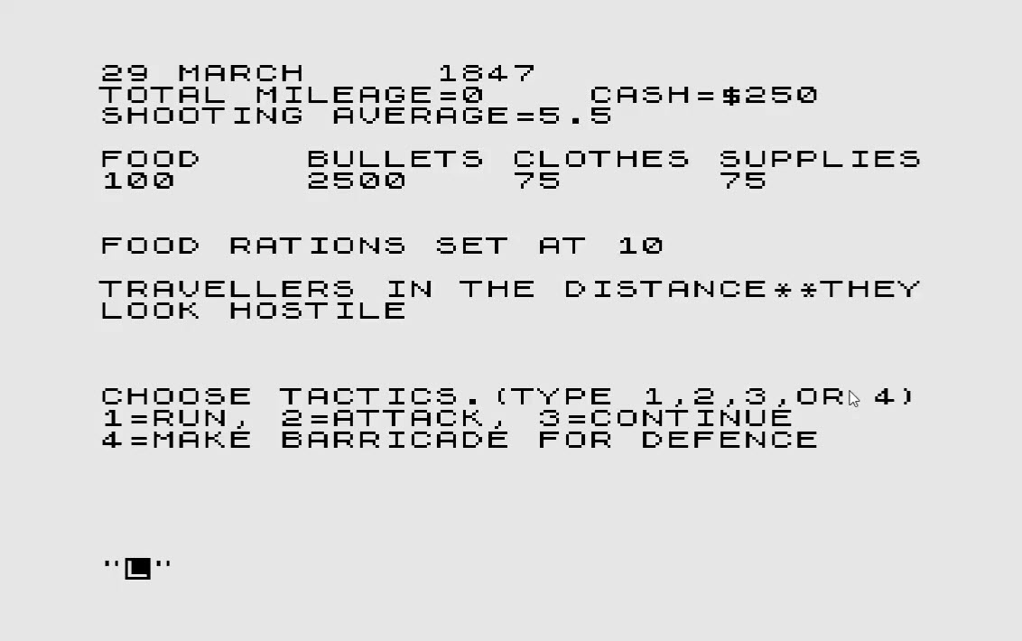
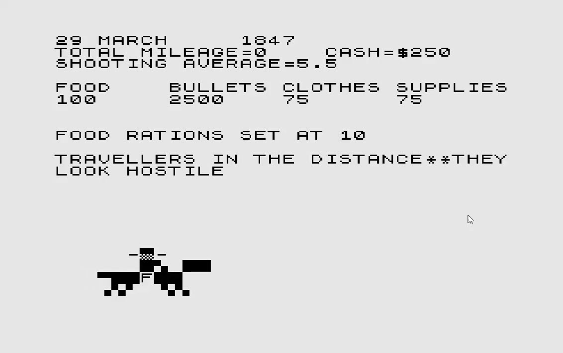
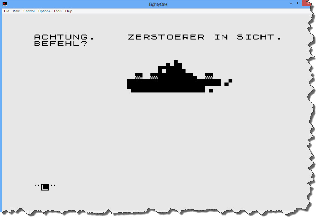 Darn – I found a Destroyer… shall we attack or dive away? – I think, we just duck away… “F” to dive.
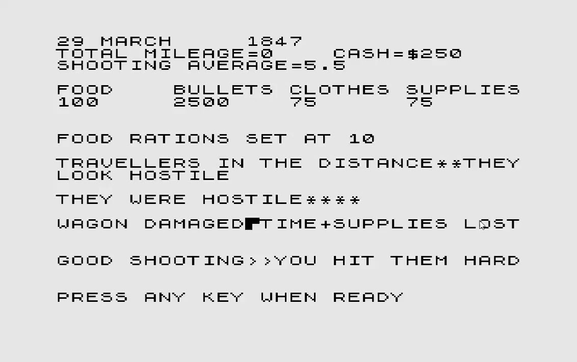
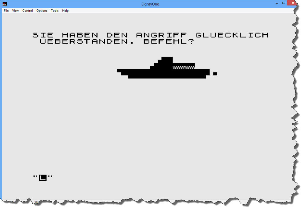 Looks like I survived the Destroyer attack – a quick look into the code reveals that, when ducking away from a Destroyer, I have a 66% chance of survival. If I’d fire a torpedo, I have a 10% chance to hit (and spend one Torpedo) – if I do not hit the Destroyer, I can still dive away (and take my 66% chance). So best strategy: fire first, then dive! Now let’s get back up again and see if there is anything else out there.
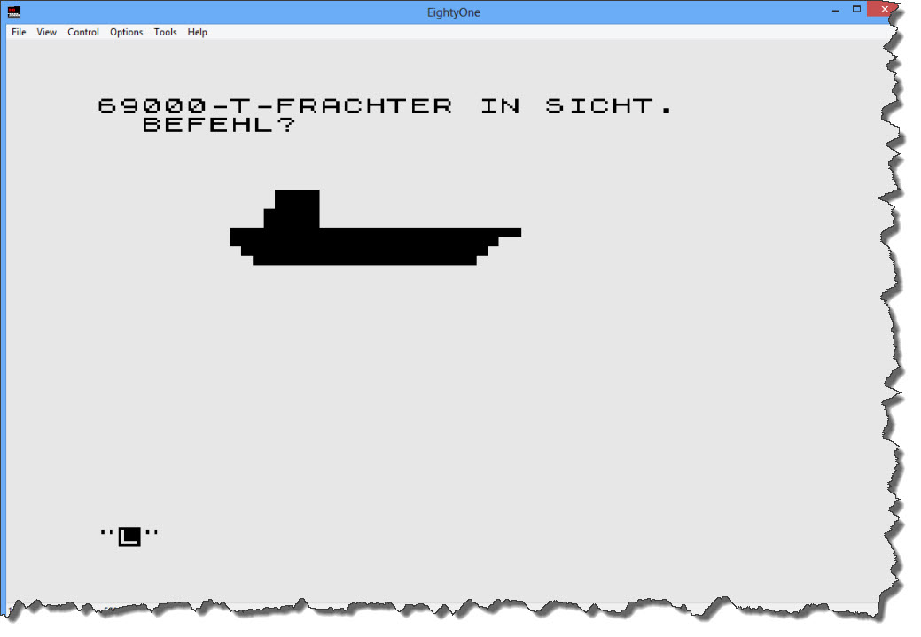 OK – a 69000 Ton Freighter – obviously, time to spend some torpedos (“T” Key). I fire two Torpedos.
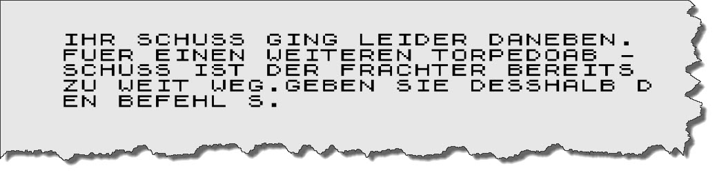
 Missed 🙁 – good for the sailors, bad for me. Looking at the code… I only have a 25% chance to hit with a torpedo (on a freighter) – that is a bit disappointing! I fire two more torpedos.
 Missed again! By now, the frighter has outrun me and I cannot fire any more torpedos. So back to the periscope (“S” Key) – another freighter, only 6500 tons though. One torpedo is sufficient.
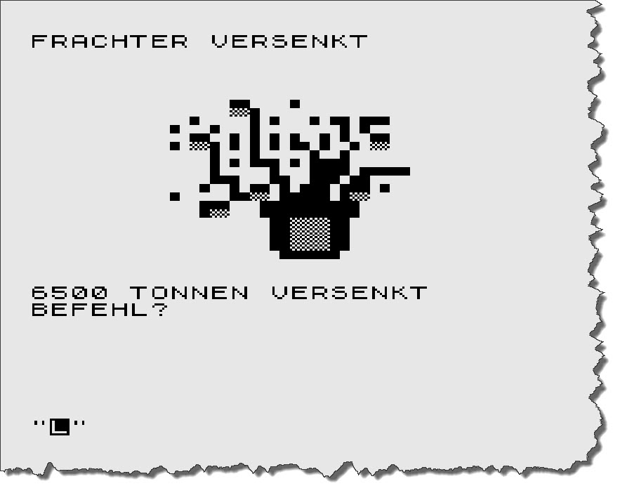 This time, I manage to score a hit – and add 6500 tons to my score. Next up is – again – a Destroyer, I fire a Torpedo, miss it and – in return – was hit by the destroyer.
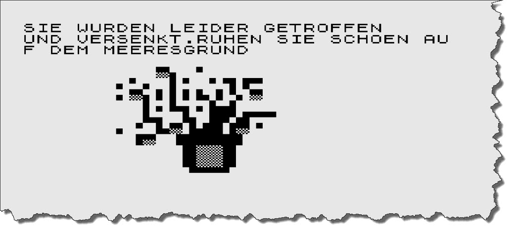 This one is ugly – the English translation is “Unfortunately, you have been hit and sunk. Have a nice rest on the ocean floor…” – Pfft!
“Playing” the game, by the way, turns out to be pretty tedious, the program is extremely picky on the commands issued: if you forget to press “T” first before you specify that you want to send “2” torpedos results in an immediate decommission… you find a freighter and accidentially hit “F” to dive… decommissioned.
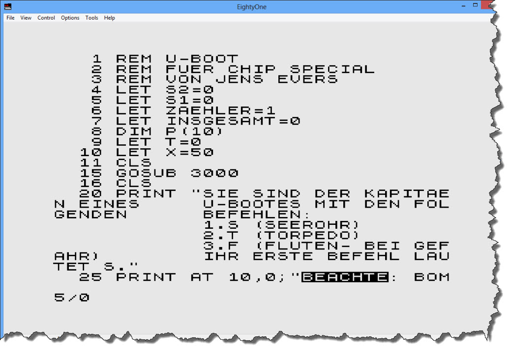
I continue to play a bit, just to also see the bomber attack that I noticed in the code – here it is:
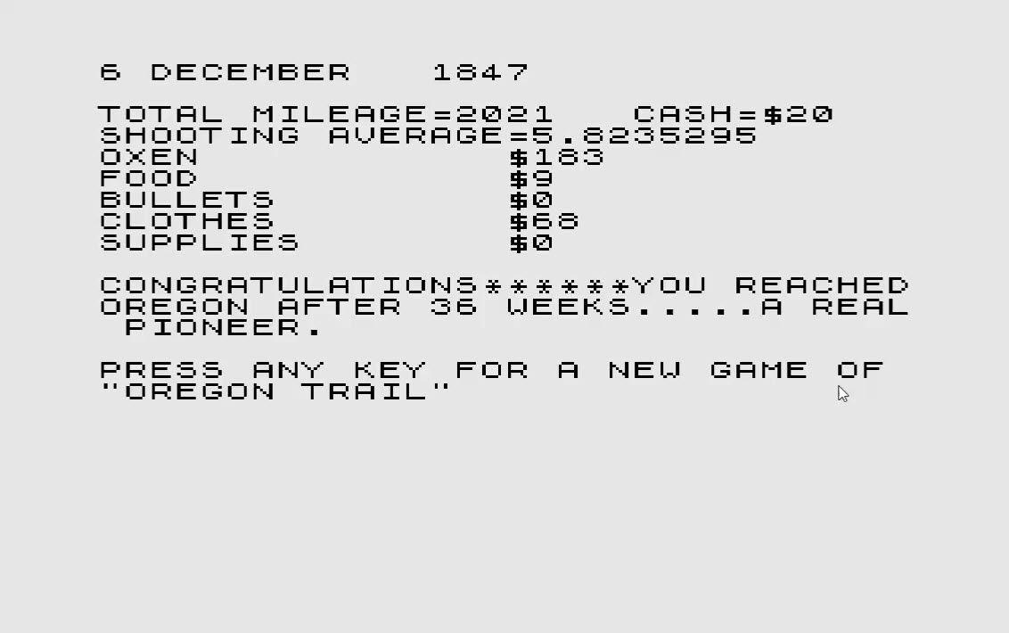
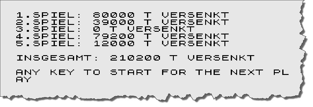
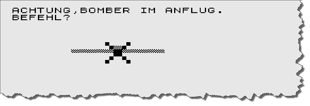 So my only choice is to dive away – “F” key! – and hope and pray. To keep the spirits high, the program is running 10 rounds (each round ends with your sinking) and shows a high-score table.
 And that is about it 🙂 – those was the content and quality of programs from computer magazines back then. This also was what the ZX81 was capable of. Still, we had plenty of fun those days and in all honesty: would anyone have shown us what computers would be like some 30 years later, we would not have believed it! But then imagine what computers will be in 30 years from now – in 2040…