I am running a second web site, dealing with specific historic aspects of the Deutsche Luftwaffe during the years 1935 – 1945. Running such a site is difficult – just to quickly one is put into a corner nobody wants to be in: the intent of the site is not glorification but a historically correct discussion of specific events or pieces of information.
As one of my “bits of information” is a collection – and discussion – of Flight Logs of Luftwaffe pilots, aircraft of different types and units are “daily business”. Photos of the time are rare, photos of specific aircraft extremely rare and color photos almost non-existing. But they say “an image is worth a thousand words” – so I decided to make up my own color profiles and create them as needed… and here is a story of how one is developed.
The Tools
One of the very first things to decide is which tools to use – as I am going to work on color profiles (not 3D-Models!) I decided to use a vector drawing program, supported by a graphics program. Since both need to work together as we will later see, the choice was easy – I am using Adobe Illustrator and Adobe Photoshop. Both are not the cheapest choice but one that works extremely well. And Adobe’s new “Creative Cloud” makes the software affordable for a reasonable monthly price.
But having the tools alone does not help – a color profile requires a decent documentation of the aircraft in question. So books (and a scanner) come in handy.
First of all, a decent drawing of the aircraft at least from the side, better from three sides is required. You can find an example for the Messerschmitt Me 210 here.
A good library is required
One is the minimum, having different alternatives is better – especially when you are dealing with aircraft that have seen many variations. The Messerschmitt Me 210 I need a color profile for was flown by the Hungarian Airforce, therefore it would have been a Me 210 Ca-1 – the variant may or may not differ from the one I got the drawing for which is a Me 210 A-1.
Good books on the Messerschmitt Me 210 are
- Heinz Mankau & Peter Petrick: Messerschmitt Bf 110 – Me 210 – Me 410, published by Aviatic Verlag, Oberhaching (ISBN: 3-925505-62-8)
- George Punka: Aircraft Number 147 – Messerschmitt Me 210/410, published by Squadron/Signal Publications (ISBN: 0-89747-320-5)
Mankau describes the Ca-1 variant as being “the Hungarian-licensed version of the C-1” which in return is described as “being like the Me 210 A-1 but using 2 x DB 605B as engines.”
So in essence, the drawing available for the Me 210 A-1 should also be applicable to the Me 210 Ca-1.
Online Resources
Another good choice are various online resources – looking for drawings of the Me 210, I have come across a site that features plenty of aircraft drawings. However, one needs to be very careful with the copyrighted material…
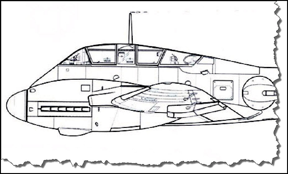
For this particular aircraft, I was able to come up with two side views, one with the engine and outer wing part, one without – excellent for properly covering the otherwise hidden areas.
Creating the Aircraft in Adobe Illustrator
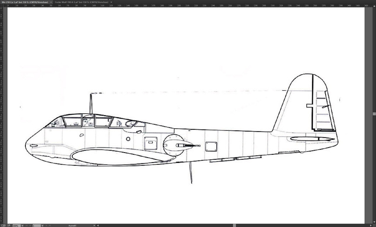
With the information at hand, the first step is to create a new drawing in Adobe Illustrator. Given my purely electronic use of the result, the choice of the physical paper dimensions is not really important but just in case, I am using A3 as paper size.
The initial layer is renamed to “Scale Drawing” and the aircraft drawing is imported, positioned and locked.
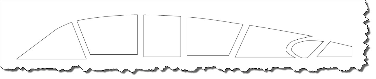
 The next step is to decide on how the aircraft is to be segmented and drawn – one has to keep in mind that the base drawing will be a “wire-frame” model, not filled with any coloring. It comes in handy to not deal with the aircraft “as one big block” but to segment it – it makes dealing with different aspects of the aircraft much easier if you know you are done with a one part and can hide it (also secure it by locking it) and – more importantly – it helps with the coloring later.
My current scheme (developed in two previous models) is to segment as follows:
- the aircraft body without any attachments such as antennas or wheels,
- the aircraft cockpit,
- the aircraft inner wing without the engines (if it is not a single-engine aircraft),
- the aircraft engine including the propeller,
- the aircraft outer wing,
- the landing gear (I usually have my color profiles “flying” so the only one that usually is needed is the tail wheel),
- the aircraft armament (guns, cannons, etc.),
- other items such as antennas, wiring, etc.
Drawing the Aircraft Body
You could start anywhere you want but for me, the aircraft body as the largest part always comes first. It also gives me the needed anchor points for other items later.
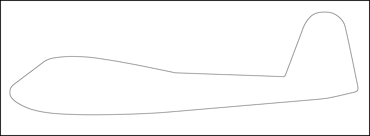
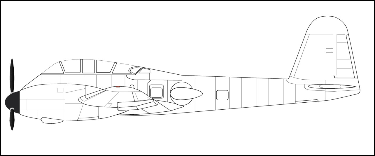
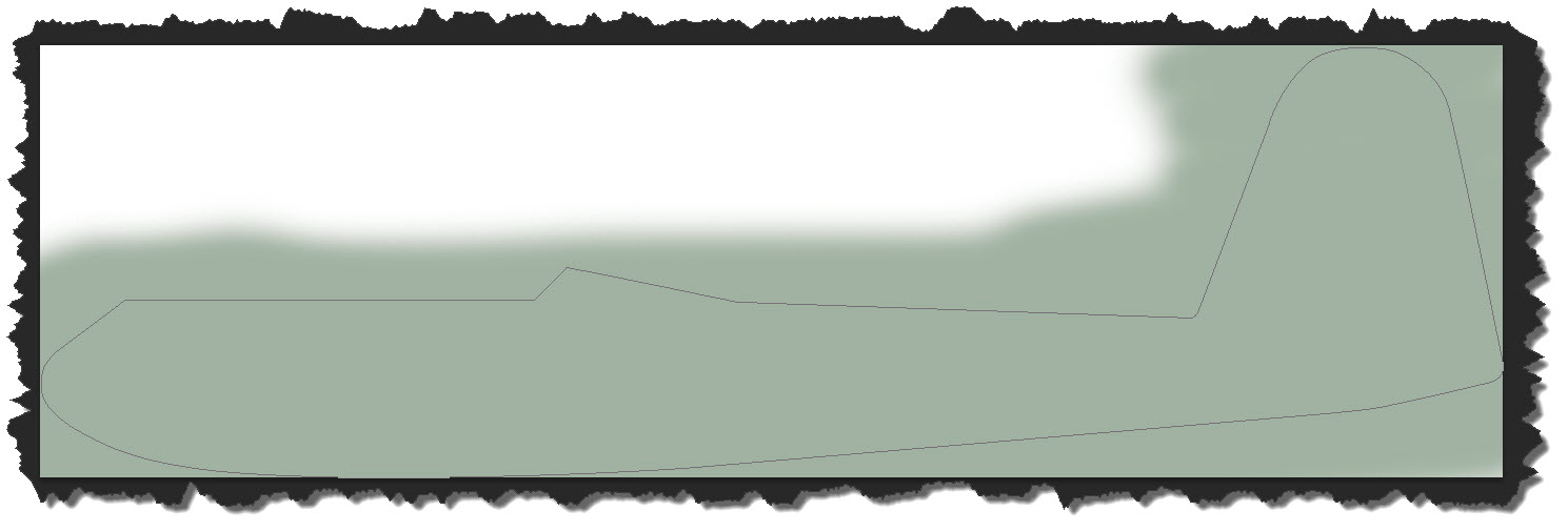
Drawing the body is easy – I add a new layer on top of the background layer, then use the Pen tool to roughly trace the outline. Also important (but my personal taste): in the first run, I don’t bother making my outline curved – I am just setting anchor points!
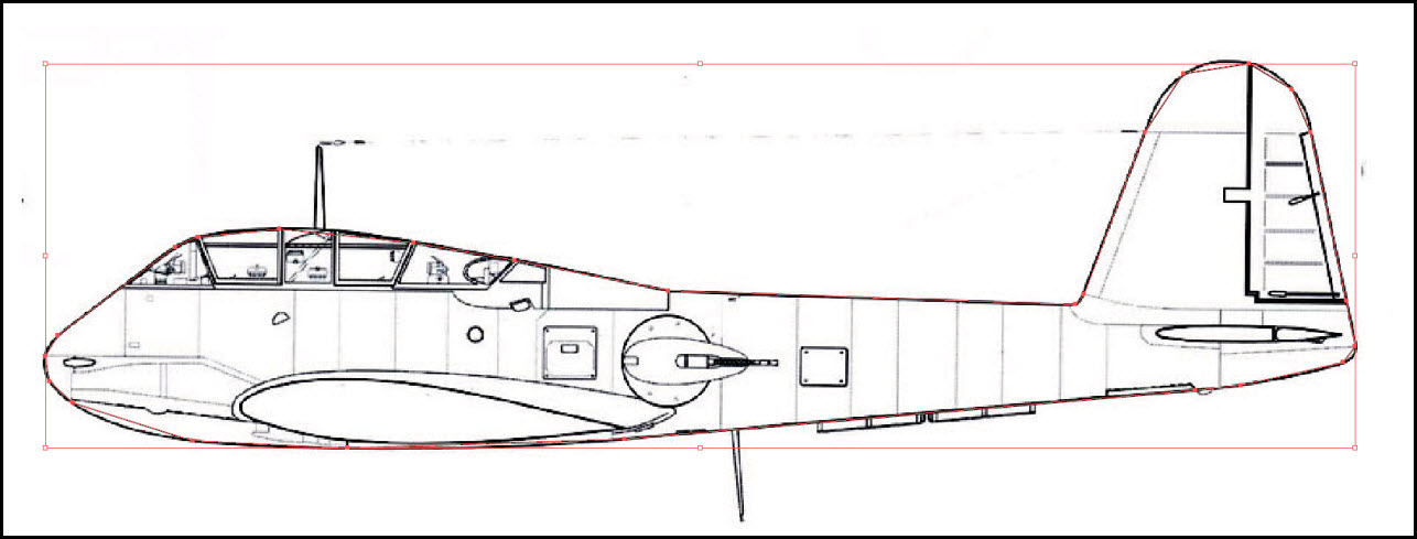
While this looks pretty good with the aircraft drawing underneath, you can see that I have not bothered to create the curves just yet – I only set the anchor points.
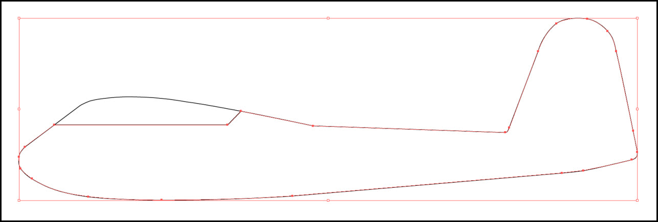
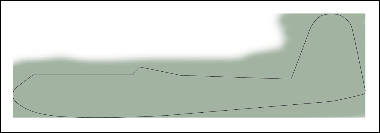
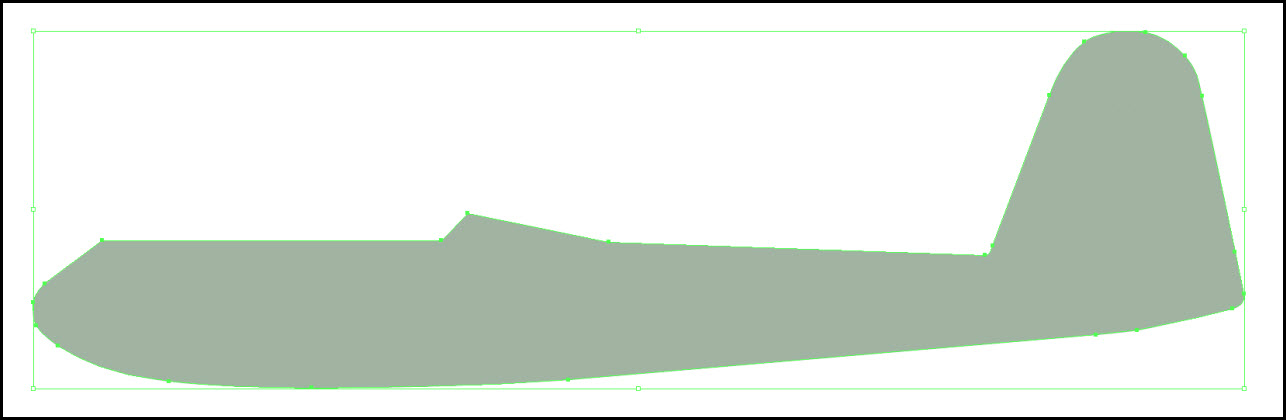
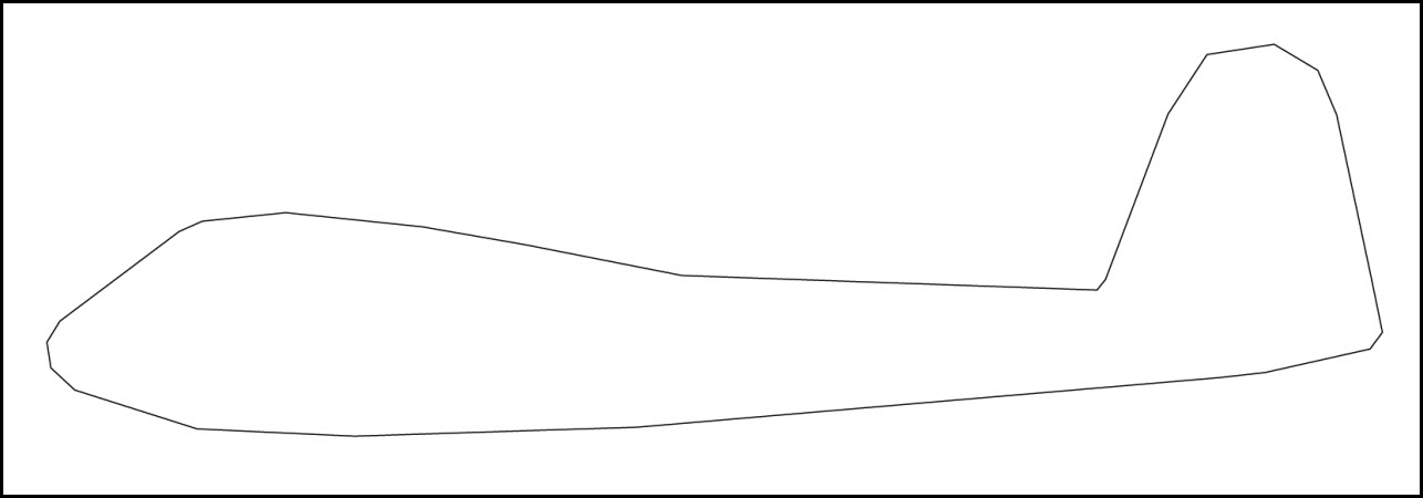 So next is making the curves – again, the Adobe Illustrator Pen too is the tool of choice, now used to turn the anchor points into curves.
 Now that does not look too bad for now – next section on is the aircraft’s cockpit…
The Aircraft’s Cockpit Section
While the aircraft body was straight forward, the cockpit section is a bit more difficult and that is because of the different materials used: first of all, the aircraft needs the cockpit frame as a separate entity because it needs coloring later. Next, the glass needs to be modeled and this, too, will receive a coloring (and transparency). Finally, the interior (at least as much as it is visible) needs to be created.
The upper part of the cockpit is currently included in the path of the Body – the lower part of the cockpit is not present. What basically needs to happen is adding a new layer – labeled “Cockpit”. Next, I will include the lower cockpit area where body and cockpit meet. Finally, I will cut the upper part from the body to complete the cockpit and at the same time include the lower part of the cockpit into the body.
Some may now ask why on earth I had included the canopy into the body in the first place – the answer is simple: Adobe Illustrator provides a smooth curving across the entire path and this is easier than creating a matching curving in two separate paths.
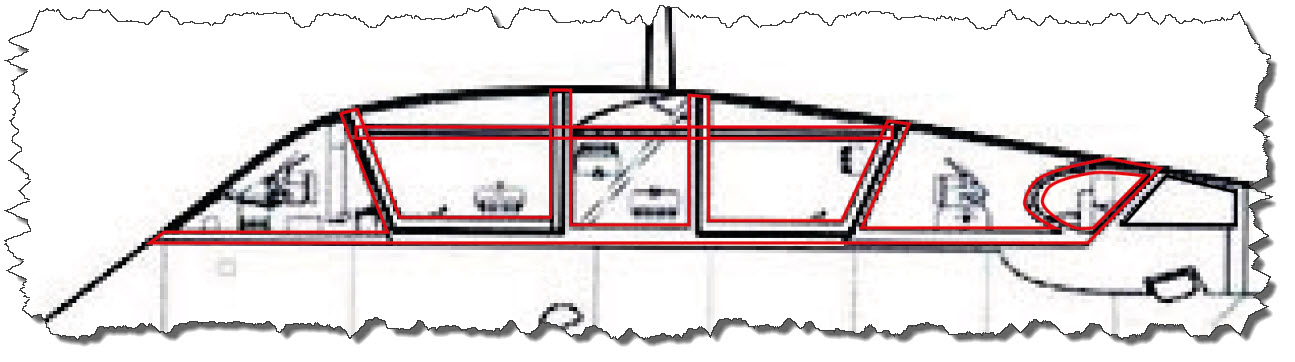
 Now it is time to finish the cockpit: the frame needs completion and the glass areas need to be cut out as separate forms to allow a different and transparent coloring. First, I create the missing outlines of the glass elements.
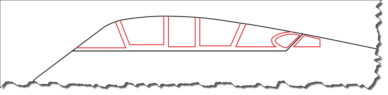 I now need to cut out the glass areas and duplicate the borders of the glass areas into the frame of the cockpit area – basically, I need the inner lines twice.
This comes down to adding missing anchor points at the intersections, cutting and joining paths and applying corrective actions. The end result is a cockpit frame…
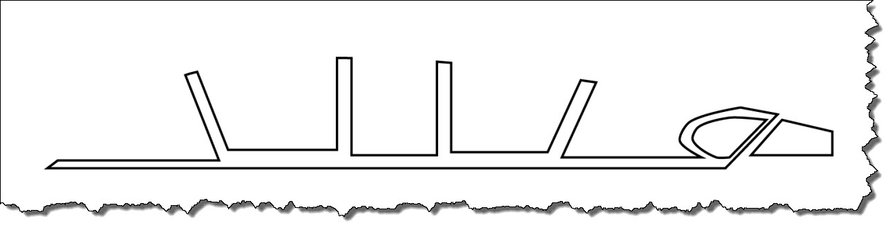 … and an area for the glass…
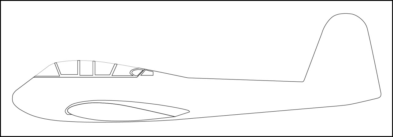
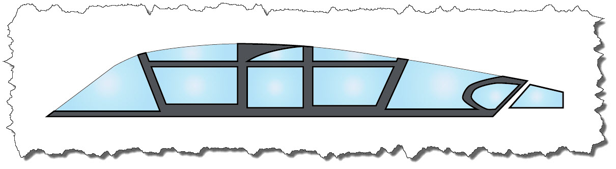
 … and both combined and with the aircraft body visible already give a nice view of the aircraft. Now on to the wing.
The Wing – a problem by itself
In my two previous color profiles, the wing had been the most difficult area to work out. Mainly because several areas are obscured and the structure itself, given the direct view from the side, is rather narrow. Minor mistakes in the original drawing result in clearly visible problems in the model. This time is different as I have two identical drawing, one with and one without the outer part of the wing an engine.
 It is now up to us – complete the aircraft body with the missing inner lines for all kinds of openings, rudder, and plating or add engine and outer wing first. I’ll opt for completing the body.
 Now, that starts to look promising… up next is the enging.
The Engine and Outer Wing
Adding the engine does not really hold anything new – again, a new layer is added, named “Engine” and again, a part of the engine will be obscured by another element, the outer wing.
Also, adding the engine requires the switching of the background image – so far, I have been working with one that did not show engine and wing but a full view of the aircraft’s body. That is now changing. To avoid confusion, I am also hiding several (actually all) vector layers I have created so far.
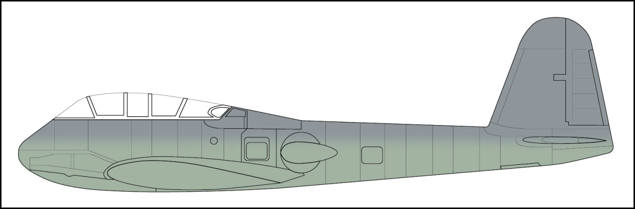
 As it turns out, creating the engine (in one layer) and the outer wing part (in a different layer) is easiest when you do it together – they share some path segments anyway. When showing the other vector layers, the previously added thin lines of the body will “shine through” the new engine block (and wing) so I have decided to fill both with pure White.
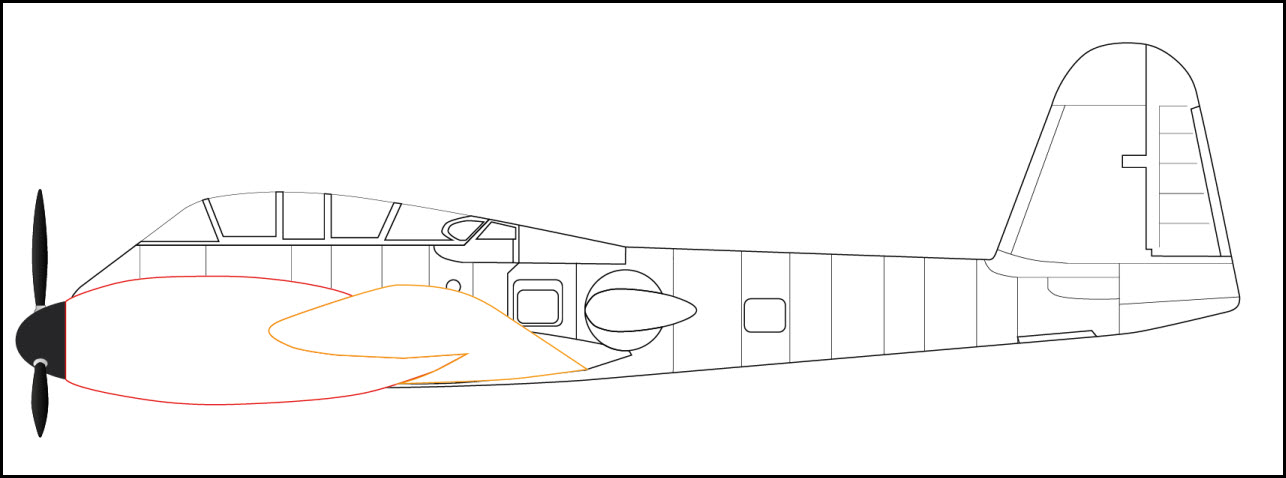 So far so good – next are the inner thin lines of both, engine and outer wing. Also the oil cooler is missing. And finally the exhaust and filter. As well as the horizontal stabilizer…
 Although the aircraft is not entirely done yet, we have enough to start adding some base color – and start with the aircraft body.
Applying a Paint Scheme – Hungarian Air Force
In Adobe Illustrator, I select the aircraft body’s outline and copy it – then I switch over to Adobe Photoshop. There, I am creating a new document with the size of the clipboard. Inserting the aircraft’s body information as Path, I end up with the outline of the Messerschmitt Me 210 in Adobe Photoshop.
Looking at samples from the various sources I mentioned before, the Hungarian Me 210 was painted in a scheme composed of the colors RLM 74/75 and RLM 76. The latter one serves as my base paint for now.
 Saving the file in Adobe Photoshop to a PSD File, I switch back to Adobe Illustrator, creating a new layer named “Color Scheme”. I copy the Aircraft’s body outline once more, inserting it into the new layer and at the same position´.
I also drag and drop the Texture PSD File from the Windows Explorer into Adobe Illustrator. Both objects should be positioned to match up.
 Finally, with both objects selected, I choose Clipping Mask -> Make from the menu. This ensures that the texture part is clipped by the form of the path.
 From that point on, the Adobe Photoshop file is linked to the Adobe Illustrator file – you should not move or rename the Photoshop file from that point on.
An interesting side-effect of that link is the automatic update – if you change the texture in Adobe Photoshop, Adobe Illustrator will recognize the change and apply it automatically. Back in Photoshop, I am now applying a layer of RLM 75, a medium gray, to the upper area of the fuselage.
 As soon as I save the file on Adobe Photoshop and switch over to Adobe Illustrator, I am asked if I want to update the texture file – confirming the update, my aircraft’s paint scheme is applied automatically.
 Next on the aircraft body is the Hungarian national colors – the Hungarian Air Force had them painted very dominantly on the aileron. Given their nature – three squares with straight-forward coloring – I have decided to create those in Adobe Illustrator rather than pain them in Photoshop.
The easiest way is to create a new layer, copy the aircraft body into the new layer, use the rest of the layers to properly place three rectangles that mark the stripes of the Hungarian flag and then use the Pathfinder tool to create a new form by using the overlapping areas. Finally, the remaining forms are filled with the respective RGB colors.
 The same way, the base coloring for the engine (upper surface in RLM 75, underside in RLM 76) and the lower part of the wing (RLM 76) needs to be applied. Both become two new Adobe Photoshop texture files.
When bringing them back into Adobe Illustrator to apply the Clipping Masks, you need to make sure though that the clipping mask is one path – in my case, the engine outline was composed of one unclosed path and one closed area so I had to create a combined path first using the Pathfinder tool. Also, you will have to place the layers more cleverly than for the body: the engine body is White to cover the underlying body areas – this needs to remain, otherwise the body will shine through.
The whole process takes a bit of fiddling around but the good thing is that once it is set up and you need to fine-tune the coloring, you are mostly dealing with Photoshop. As long as you keep the linked file the same, you can do anything you want – including working with different Photoshop layers that you can hide or show and even those settings will carry over to Adobe Illustrator.
 So if things don’t work out the first time, don’t worry – corrections are not too bad the way both tools interact.
Speaking of “corrective actions” – there is one big error to fix on the aircraft: the cockpit section does not yet have its horizontal bracings yet. So let’s rework the cockpit area. But before doing so, there is one more important aspect to mention – and that is keeping control of your files altogether.
Version Control
There is nothing worse than losing work – one way to do so is to forget to save when Adobe Illustrator decides to crash on you – happened twice (the crash) while I was working on the Me 210. There is no native auto-save feature built-it so you either have to find a different way or remember to save your work frequently.
The other way of losing your work is by saving… sounds funny? Not necessarily if you keep in mind that saving a file means overwriting the previous version. Like in the situation I am in now: I have a well-modeled cockpit area and I am going to make a major change. As soon as I save, the old “version” is overwritten – what if I ever have to go back?
Well, one way certainly would be to do a “Save as…” but that will create a ton of files with different naming and I would not be able to do this for the Photoshop files as their name is linked to the Illustrator file. So my solution is to use a Content Management System (or better: a Revision Control System). My files are stored in a Subversion Repository which allows me to keep the history of my development and always only work with one file (but always also be able to retrieve any previous version I might need).
Corrective Actions – the Model
As mentioned above, my cockpit section requires some rework. My files are securely stored in Subversion and I am free to re-work the cockpit as needed. So here is the original cockpit section.
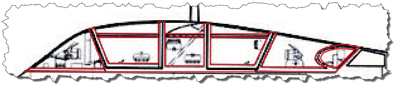
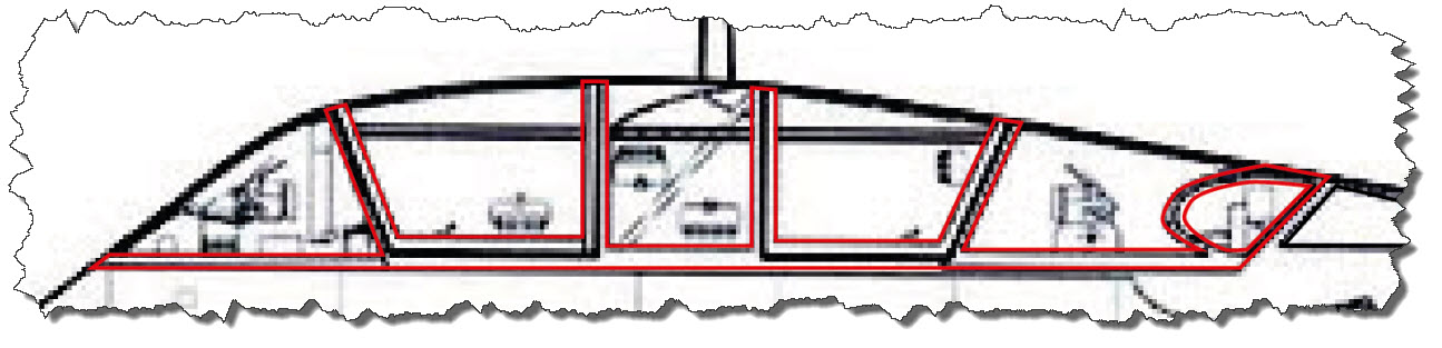 As you can see from the underlying window, there is a horizontal stabilizer that I forgot to put in. Also, the middle section’s top area is not entirely made of glass – there is a metal area in the upper left part of it.
The horizontal bar is easily put it. I just draw a rectangle where the bar needs to go (and make sure that both ends are well within the existing structure).
 Next, I use the Pathfinder tool in Adobe Illustrator to merge both areas and form one path from them.
 I can now to the same for the central section of the cockpit, making it a 50-50 structure of glass and metal. Finally, the glass and the new frame need to be worked out so every glass part is also available as closed area for coloring. Finally, the cockpit frame needs an Adobe Photoshop texture.
 But that coloring is incorrect – the aircraft now gets a bit tricky: the canopy area is a mix of RLM 75 and RLM 76 (latter one being the lighter gray) and the RLM 75 area continues into the main part of the body. But using Adobe Photoshop and different layers for the coloring, even this pain scheme is easily applied.
 Corrective Actions – the Coloring
We have already seen a bit of the coloring being reworked in the past few steps. But now, it is time to take things a but further but that, I am afraid, takes us deeper into Adobe Photoshop. Remember: once the actual texture file has been applied, all changes made to it in Adobe Photoshop are automatically carried over to the Adobe Illustrator drawing. And that will now play out quite strongly…
Remember the initial coloring of the body? I have to admit: I have taken a very easy approach to not add complexity at that time. But now, I am at a point where things need to get a bit more into detail.
Initially, I had selected the outline of the aircraft’s body and pasted it into Adobe Photoshop as a new Path – the disadvantage is, that this one will vanish when you close and re-open the document. Instead, it is better to paste the outline as Smart Object, which will create a new Adobe Photoshop Vector layer. This one remains with the document and should immediately be locked.
Next, I applied all coloring to the base layer of the Adobe Photoshop document. It would be better to do that in a separate layer as well (not necessarily but for example if you would try the difference between different shades.
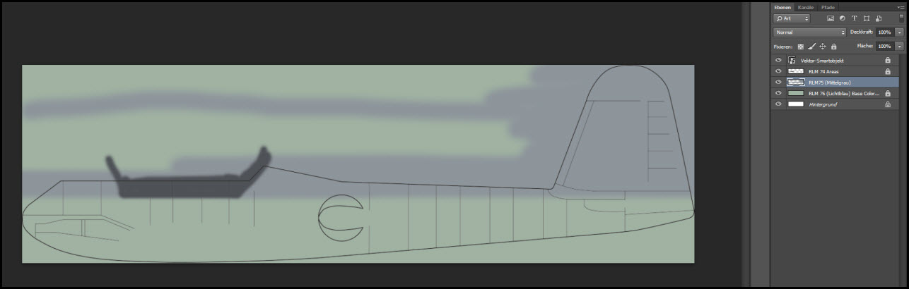 Notice the layers (German: “Ebenen”) on the right? There is an RLM76 Base Coloring layer… now I think my RLM76 is a bit to “greenish” but RLM76 seems to have come in variants… so let’s try the two more “grayish” ones… just adding a separate layer and then handling the visibility in Photoshop makes the Adobe Illustrator work change.
 As you can see in the Adobe Photoshop Layer tool, I am now working with several layers, some of them being visible, others not.
This way, I can control the texture and experiment with the colors without ruining work done before.
Also important: for the final usage in Adobe Illustrator, you need to hide the Vector-Smartobject (the outline), otherwise you will end up with duplicate lines.
Another advantage of the use of layers is that they can easily be moved. Think about the RLM74 layer (this is the one holding the dark gray section around the cockpit): it might be perfectly shaped but a bit out of position in the final rendering – how cool is it to just move the layer around without messing up any other parts of the texture?
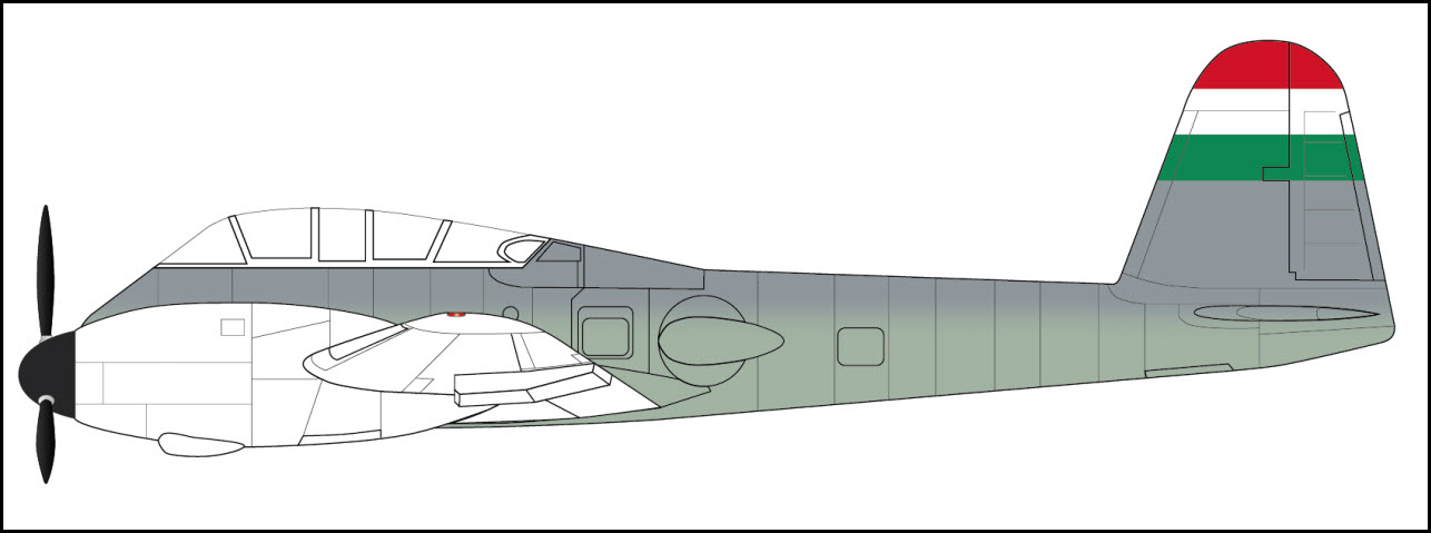
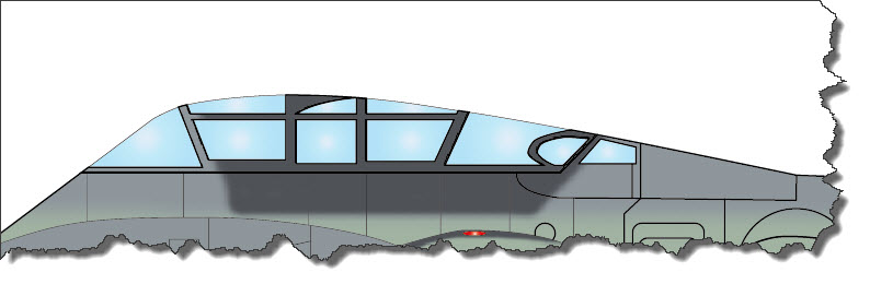
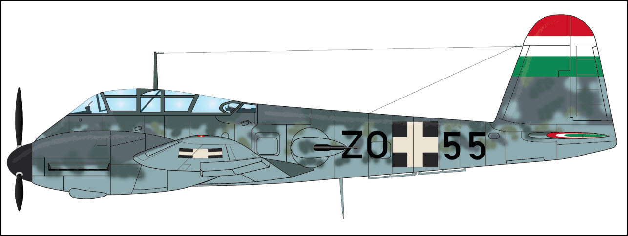
Eventually, one will find out that it is quite difficult to find “the correct coloring” for the aircraft: the theories which colors have been used and what exactly they have looked like are as unified as the weather forecast for next month… so at the end of the day, I have decided to settle on a color scheme that seems “reasonable” – and there is the result:
 And yes, there has been another correction applied – the incorrectly placed “bent” in the upper aircraft body (which was present in the Me 210 A-0) was removed.
Final touches
You have seen most of the techniques applied by now – there are some finishing touches that remain open like the Hungarian Air Force markings, antennas, exhausts, guns, horizontal stabilizer, cockpit interior… and finally some light effects to prevent the drawing from looking too flat…
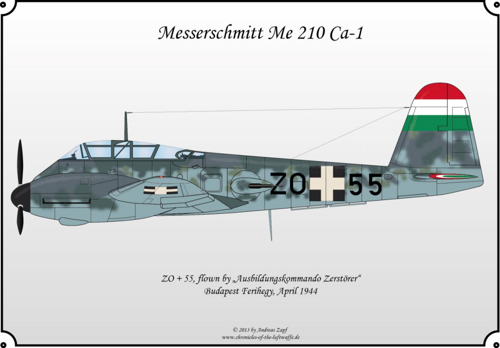
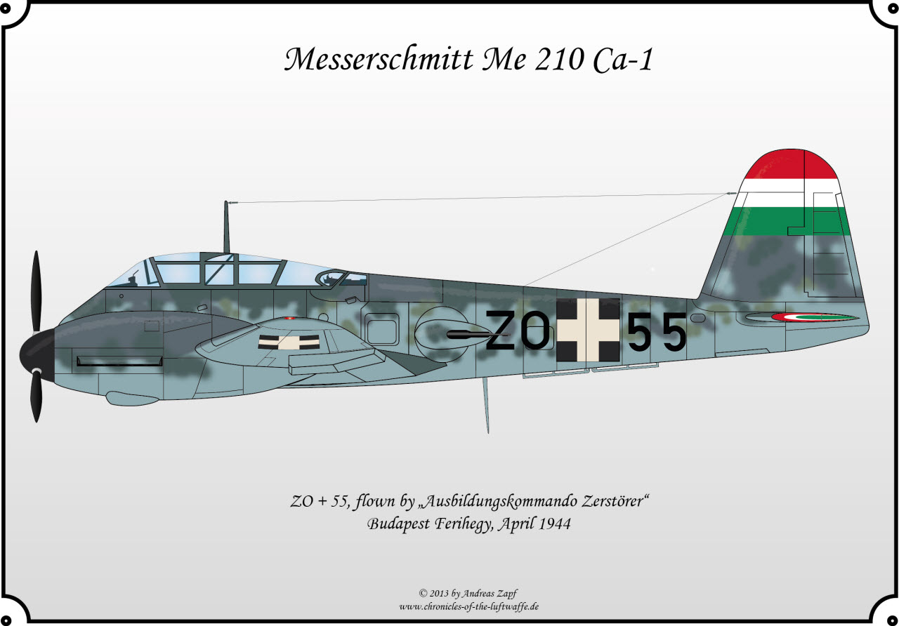
 Giving it all a Frame
Coming to an end, the last remaining item to be done now is to add a decent frame to the aircraft drawing – presentation is everything…
 Some closing Comments
It is almost surreal but despite these aircraft not being older than 70 years, it is hard to get a definite “this is how she looked” type of drawing. With respect to the model itself, the aircraft frame: that is well documented… plenty of photos and drawing out there but hey, even there the trouble starts: if there had been different variants of an aircraft, which one is the correct one? How does that particular variant differ from another one? You may find all the information required in the literature – but you need to crosscheck them all because the book you are looking at might have that small error itself…
The coloring is an entire nightmare – believe it or not, the interpretation of the defined RLM Colors used by the Luftwaffe are as different as day and night. Unfortunately, very few color photos exist – those that exists had seven decades to fade the colors – plus the film use to take the image may have been exposed to heat, cold, etc. – so all in all, an assumption on the colors can be made – but that is it. A definite “this is what she looked like” is impossible – but a whole-heartedly “this is what she might have looked like!” is quite possible.
Finally, there is the level of detail – every artist is applying a different one – some want to draw every single item, no matter how small or how hidden it is – others tend to focus on the overall image. Neither one of them is right or wrong, this is artwork in the best possible sense and artwork is always an interpretation of the artist… so forgive me (and anyone else trying to put out color plates, scale models, etc.) if you would have done it differently – this is the way I did it and I can only encourage you to enjoy… provide feedback, constructive and encouraging and I will adapt as I see it fit…..