The Goal
As part of my learning curve with Blender, I have come across several brilliant tutorials on the Internet – one, that I particularly liked was two videos (in German language) on the creation of a dice (Video 1, Video 2). Thanks to Berthold Lausch for the great job!
As much as I enjoyed the two videos – I initially had some trouble getting to follow them because some things had not been “obvious” to a newbie like me. So I decided to pick up where I felt the videos had lost me and put them into my own little scene.
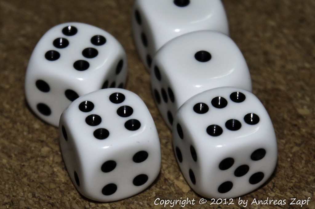 This is a pretty good roll – besides that, it is also a pretty good thing to model in Blender as a beginners work (especially with the help of Berthold’s tutorial!) – so let’s get at it.
Modeling the base Form
When Blender starts up and loads the factory settings (which you can enforce by going to the File menu and select Load Factory Settings) you will see that three objects are already present:
- a light source,
- a camera, and
- a basic cube
Which is a good starting point since we are going to use the existing cube and turn it into the first dice. Those of you that are used to technical drawing using 3-side-views might appreciate the keyboard shortcut Ctrl-Alt-Q which switches the screen layout to a quad-view showing the top, front and right sides of the scene as well as a 3D image from the positioned camera.
The first thing Berthold is doing in his tutorial is to select the cube – just use the Key-A to Select All. Your cube should be highlighted now.
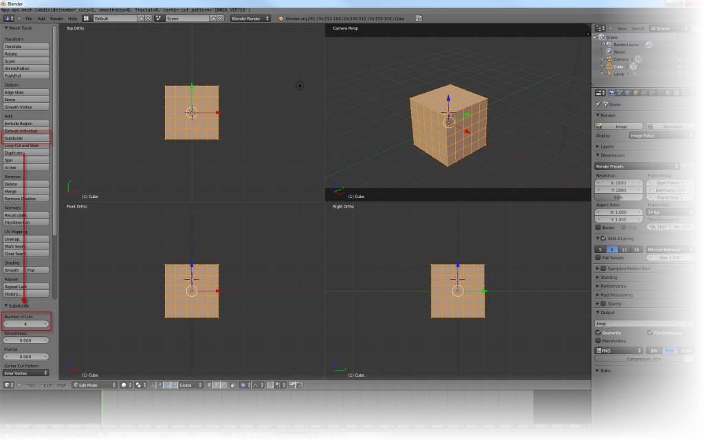
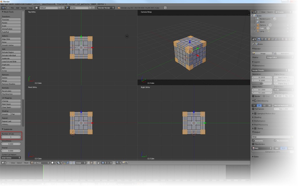
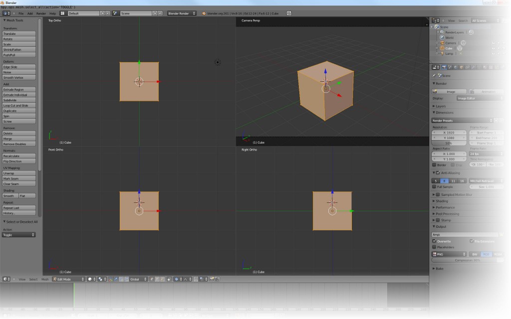 The next step then is to subdivide the existing cube into smaller elements – if your Mesh Tools are visible, just click the Subdivide button, if not, press Key-T to show the Mesh Tools.
Berthold is using Number of Cuts = 4, actually dividing the cube into 5 divisions across. After having run through the tutorial, I figured out that that is the best number to work with because it will later help us to easily place the pips in the dice.
 The next step has taken me a while to figure out – because of the way Blender handles the selection of object. What Berthold is showing in the video is the subdivision of the cubes that form the edges of the dice. We need them to become more granular so we can model the curves of these edges. There are a couple of steps to go through:
The first thing to do is to switch from the Vertex Select Mode to the Edge Select Mode.
 Next, you clear the selection by simply using the Key-A again – it toggles between Select All and Select Nothing. So make sure the cube is gray (which is “not selected”).
Then, you need to select the edges: first of all, I think the key combination Ctrl-Alt-Shift is already a finger breaker (but it seems like you need it for this step) – and this is because of the different selection modes in Blender:
- Simple Right-Mouse-Button Click (RMB) selects the object beneath the cursor. If something else was selected, it is no more.
- Selecting using Shift-RMB adds the object under the cursor to the current selection – this is how you can select multiple objects at a time.
- In Edge Selection Mode (as we are), Ctrl+Alt+RMB invokes a “Edge Ring Selection” – you can find all the details here.
Bottom line: to select the cubes forming the edges, you need the Ctrl+Alt+RMB combination for the Edge Ring Selection and the Shift key in there to add to the selection. Then you need to click the wire frame lines that form the edges. I have marked the click-spots with red arrows for reference:
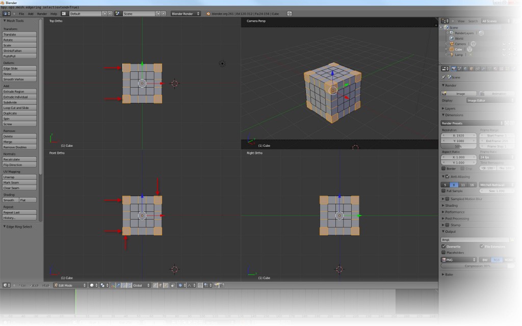 With this selection, click the Subdivide button again and use Number of Cuts = 1.
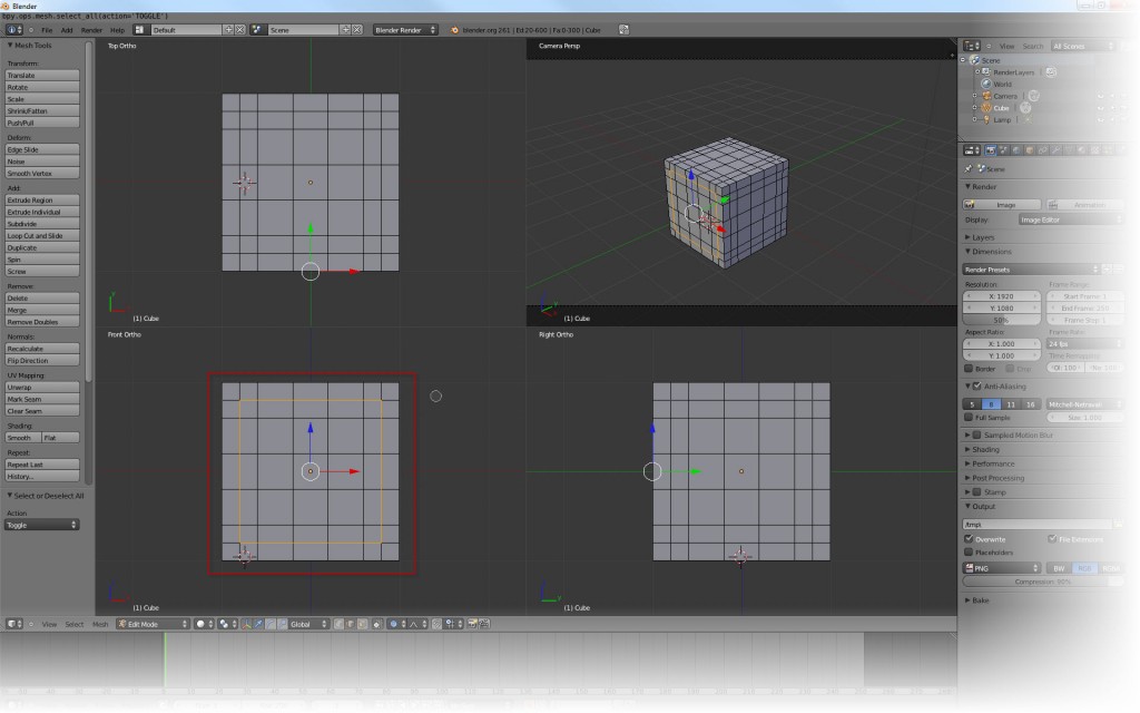
 Now, we need to form the rounded area that makes the pip areas up. Berthold is doing this the following way: while still in Edge Select Mode, clear the current selection – Key-A – and then press Key-C to enable the Circle Select tool.
The Circle Select tool provides you with a circle on the screen and everything that is within the circle when you click the Left Mouse Button (LMB) is selected. You can use the mouse wheel to make that circle larger or smaller. So select the outermost ring by clicking the individual line segments. By the way: if you accidentally select the wrong segment, click it with the Middle Mouse Button (MMB) – which sometimes is the wheel itself. When everything is selected, use RMB to exit the Circle Select mode!
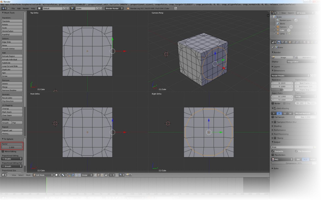
 Berthold is now transforming the selected rectangle into a sphere – you can use the Mesh -> Transform -> to Sphere menu. Or just click Shift+Alt+S. Either way, you are now having your selection transformed into a sphere. If you move the mouse, you can see the sphere shaping differently – you want a Factor = 1… but where to set it?
There seems to be a small bug (or at least non-intuitive behavior) here: you need to move the mouse over to the Mesh Tools window and actually click into it to get the text input field for the To Sphere Factor.
 Now, we have done three sides of our dice – we need to do three more side. The problem is: they are hidden in the Quad View – and we cannot see them. If you have been peeking and poking around blender a bit, you know that the individual windows can be set to different view-ports – at the moment, the view-ports are setup (starting in the upper right corner, going clockwise) as Camera, Right, Front and Top.
You can change the view-port of each individual window using the Num-Pad (on the PC):
- Numpad-7 is Top View,
- Numpad-1 is Front View,
- Numpad-3 is Right View, and
- Numpad-0 is Camera View
However, in the current setup, only the upper right window allows us to change the view-port. Why? Well: as I had to find out here, Quad View (which I have been working in) locks the other three windows by default. To unlock them, press Key-N to display the Properties and un-tick the Lock item in the Display section.
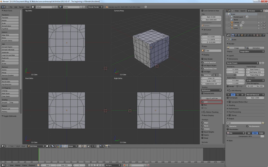 With the lock removed and the understanding that the Numpad-Keys combined with the Ctrl-Key toggle the view-port to the opposite (so Numpad-7 is Top View, Ctrl-Numpad-7 is Bottom View) you can now move the cursor over the individual windows to toggle the view to the opposite sides.
Once all six sides have been treated and their sphere transformation is through, you are almost halfway there. Next step Berthold is taking us through is the actual shaping of the edges: with the Edge Select Mode still switched on, we are now going to select the dice’s edges. Remember the Ctrl+Alt+Shift+RMB finger-breaker – the click-spots are in the screen-shot below:
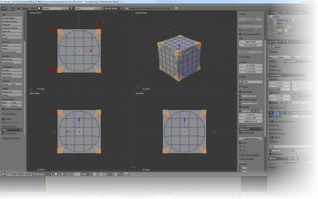 This selection is also transformed into a sphere – a logic not immediately understandable but if you imagine just having selected a portion of the entire cube for transformation (the selected edges) and transforming these into a sphere while the plain areas remain plain, you can see where this is coming from. Play a little bit with the mouse to see the effect of the different factors but finally use a To Sphere Factor = 0.8 to stick to Berthold’s tutorial video (after all, these are his steps!).
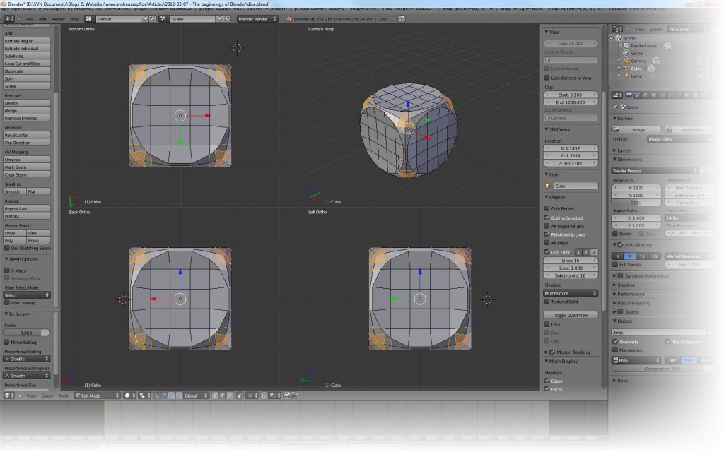 As you can see, the inner areas of the dice are now slightly “indented” – a victim of transformation. Berthold is showing us a quick way of correcting this problem – by using the Snap Tool:
 First, enable snapping by clicking the little magnet icon. From the selection to its right, select Vertex because this is what we will be snapping to. Finally, select Closest as the target.
Now, select the Face Select Mode – the icon to the right of the Edge Select Mode. Then toggle away from the Quad View and rotate the dice so you can see three of its sides. Finally, press Key-C to enable the Circle Select Tool.
Now, select the nine faces on one side of the dice and exit the select mode by clicking RMB. Your screen should now look like this:
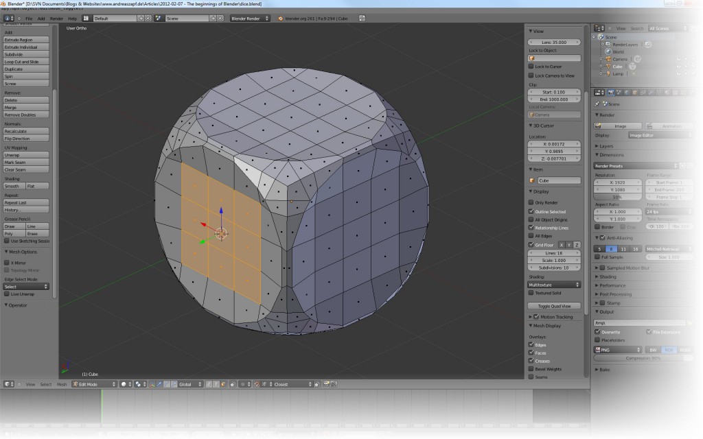 The next step is tricky: notice the axis indicator in the lower left corner? The faces selected in the above image need to be shifted along the Y-Axis. So press LMB (and keep it pressed!) and press KEY-Y. This locks the movement to the Y-Axis. Now move the mouse to the position indicated in the image below and you will see a small white circle – the Snap Indicator. This is where your faces will snap to if you release LMB.
Note: Instead of locking the axis as described above, you can drag the appropriate axis by clicking & dragging it on its indicator (the green arrow in my case).
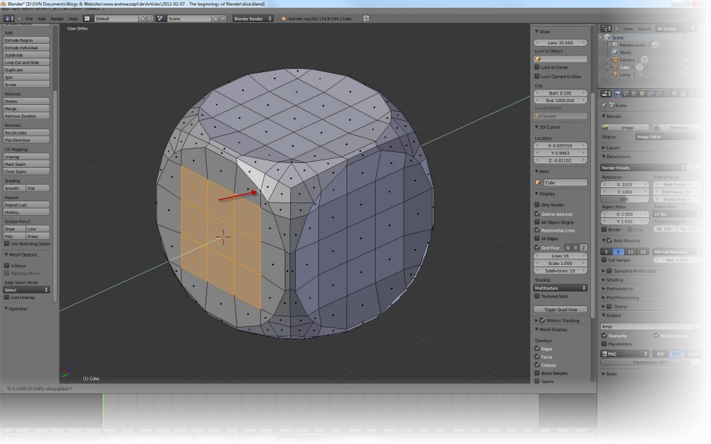 Repeat this for the remaining five sides of the dice by rotating the dice in the view as required. Eventually, you will end up with all six sides being aligned.
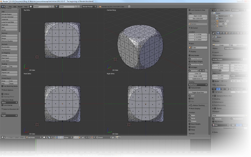 Which leaves us with the next task – creating the pips. First of all, disable the Snap Mode in the toolbar. Then take a look at the dice. In my screenshot, we are currently seeing the Top, the Front and the Right side.
Now, switch to Circle Select mode by pressing Key-C and let’s say the Top side becomes our value 6. From the nice center faces, now select those that are going to form the 6.
 Now continue with the other faces – the Front (which will be our 4) and the Right (which will become the 5). Use the 3D View to verify things work out the way you want. While in Circle Select Mode, you do not need to press the Shift Key to add to your selection…
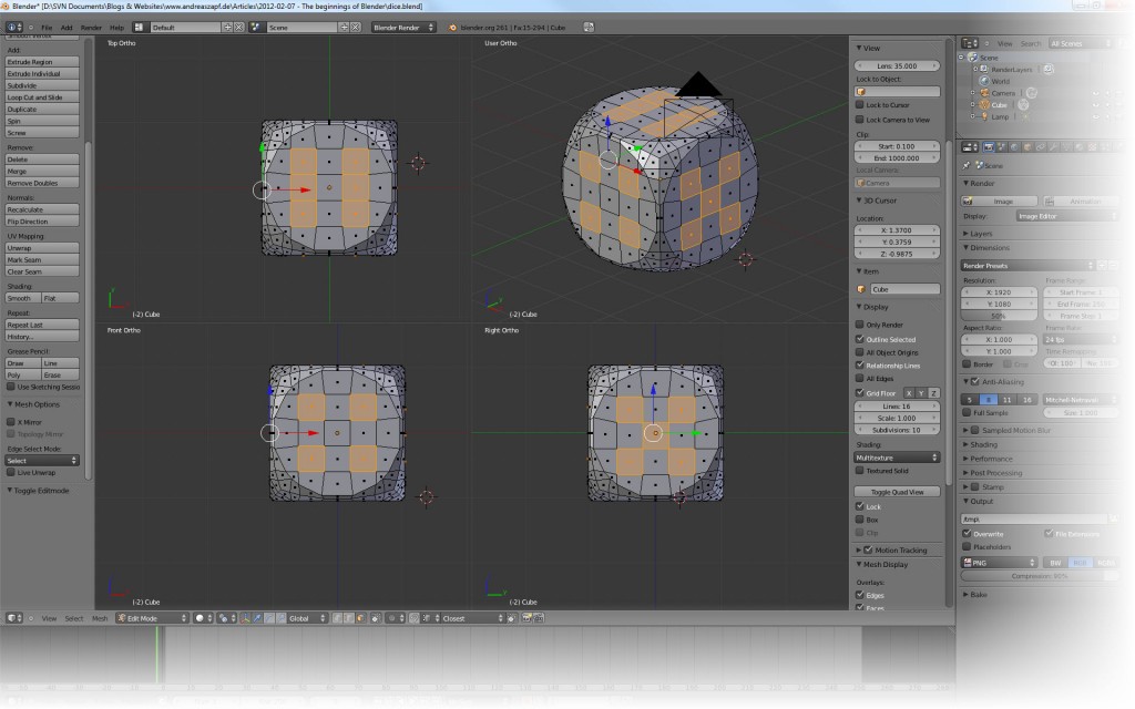 The three sides we have defined also define the remaining sides of the dice as the sum of pip on opposite sides always equals 7. To see the three other sides of the dice, use the Numpad Key to rotate
- Num-7 and Ctrl-Num-3 rotate the top-left window (as Numpad-7 is the top-left button on the Numpad),
- Numpad-1 and Ctrl-Numpad-1 rotate the lower left window, and
- Numpad 3 and Ctrl-Numpad-3 rotate the lower right window.
So go ahead and do the work. Use the 3D View to make sure all sides are properly selected.
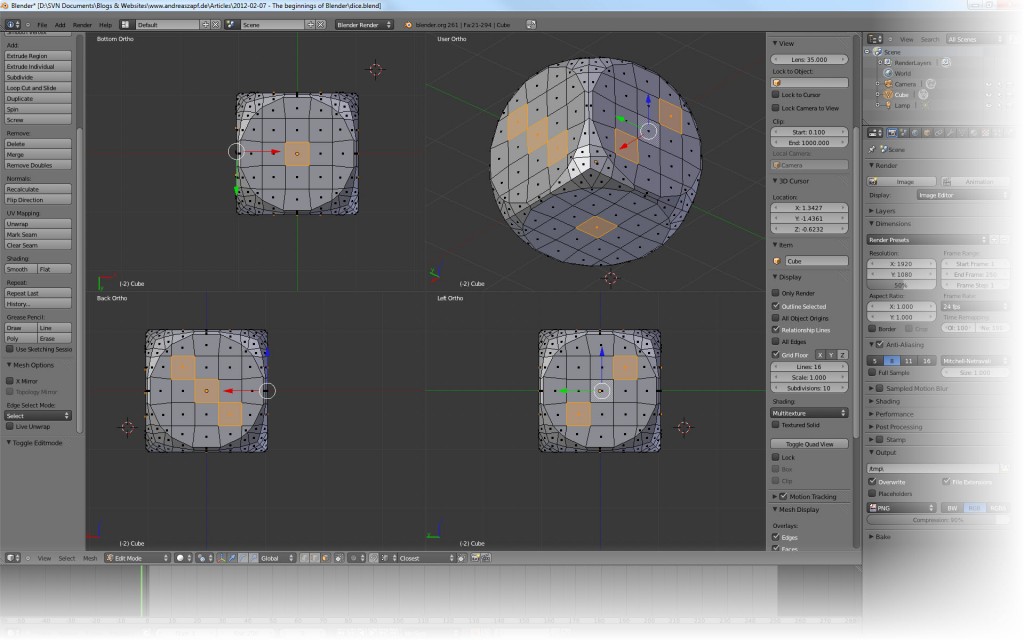 I now switch my display from a Solid View to a Wireframe View using the window menu.
 This makes an interesting view as we can now clearly see the selected faces and how they are absolutely aligned on the opposite sides.
Note: I had to cheat a bit while writing this down because the moment I switched to Wireframe View, it became obvious that something along the line had gone wrong: my pips had not been properly aligned… I had to redo the circle quickly but it emphasizes the need for frequent saving of your work: had I saved after each step and had I saved to different files (which Blender supports quite easily) I could have gone back, figured out where the error occurred and could have picked up from there…
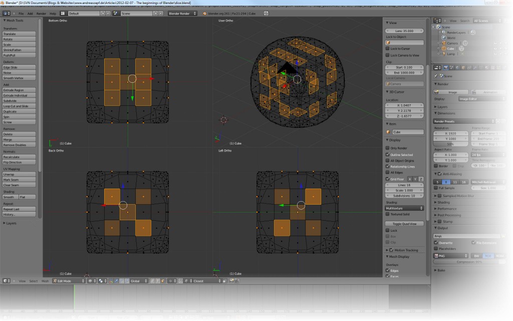 Next, we are going to extrude the selected faces. Press Alt+E to get the Extrusion Menu, select Individual Faces and immediately cancel the operation without moving the mouse.
 Matter of fact, you will barely see anything – certainly not in the 3D View because you did not really extrude anything. But you can see the change in the three other views – the faces are now presented as lines.
Now hit Key-S to initiate Scaling. Scale the faces just ever so slightly in.You can control this best in the wireframe view because you can tell the distance of the face from the edge.
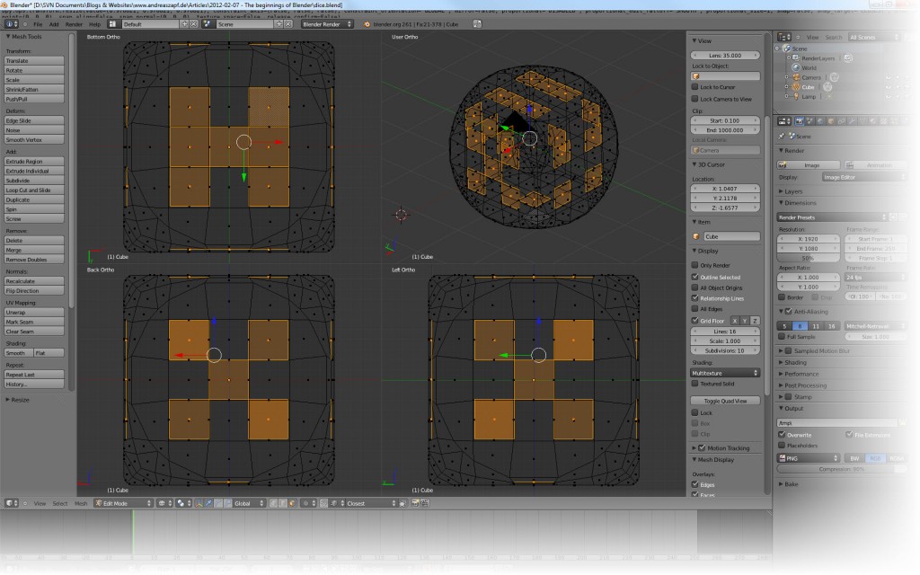 Now repeat those two steps on the selected faces – Alt+E to get the Extrude Menu, extrude Individual Faces – this time, move them really slightly towards the center. Then repeat the scaling once more.
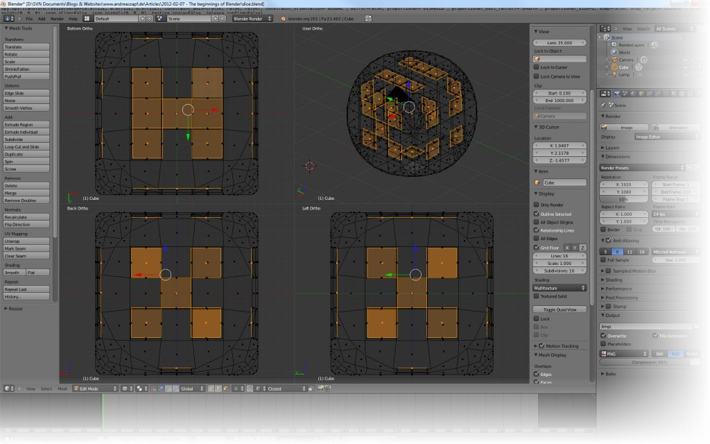 Next, use Ctrl+Numpad+Plus exactly one time(!) to extend the selection. Doing this once select the next level of the dips.
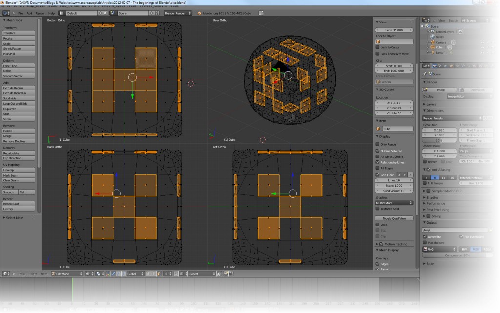 We are now holding the pips in our selection – not only the base level of the pip but also the “sides”. Time to apply some material. Switch back from Wireframe View to Solid View.
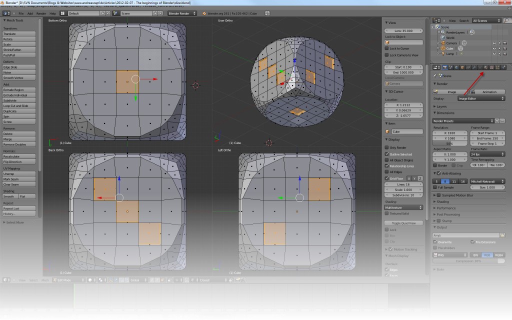 And now click the Material button as indicated in the screenshot above. Make the following changes:
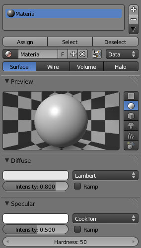 With the first Material selected (there is only one) in the list on the top, you can change the name of the material (the text box beneath the Assign button).
Name the Material “Dice”. Click the white field in the Diffuse section to select a color – something white or pearly, as you like. This will be the color of the dice.
Then back to the top with the list of Materials. Click the Add new Material button – the Plus sign on the right.
Below the Assign button, there will be a New button which you need to click as we are creating a new material. Name it “Pip”.
Click the color area in the Diffuse section. Move the black & white slider on the right all the way to black – this will be the color of our pips. Next, in the Specular section, set the Intensity from 0.500 to 0.800. The whole material area should now be looking like this:
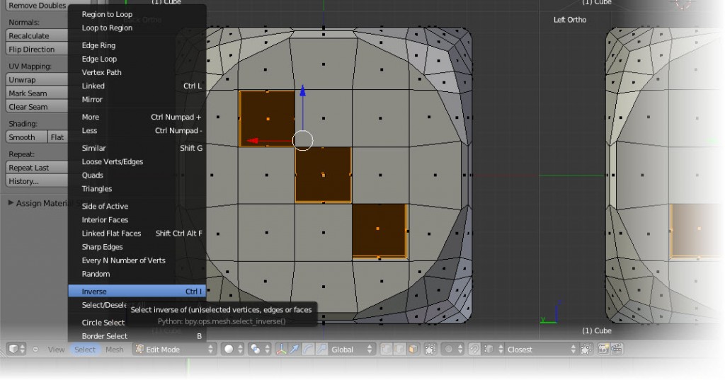
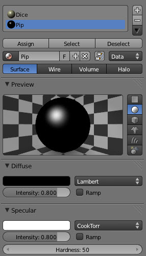 Now, with the pips still in our selection, make sure the Pip Material is active and click the Assign button. If you are displaying the Solid View, you can now see the pips being dark. From the Select Menu, use Select Inverse to select exactly the remaining – currently unselected – faces of the dice (and release the selection on the currently selected ones). This will select anything but the pips…
 Now select the Dice Material and click the Assign button again… And there we go.
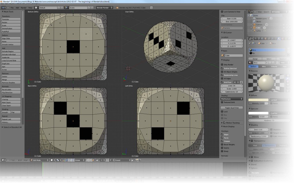 Still a little “edgy” – but that can be helped quickly. To sort out the edges, we are going to add an Object Modifier which is – in detail – explained here. The one we want is called Subdivision Surface.
 So click the appropriate Object Modifiers Button as indicated in the screenshot above. Then click the Add Modifier Button which appears. Select Subdivision Surface from the List. This already smooths the dice.
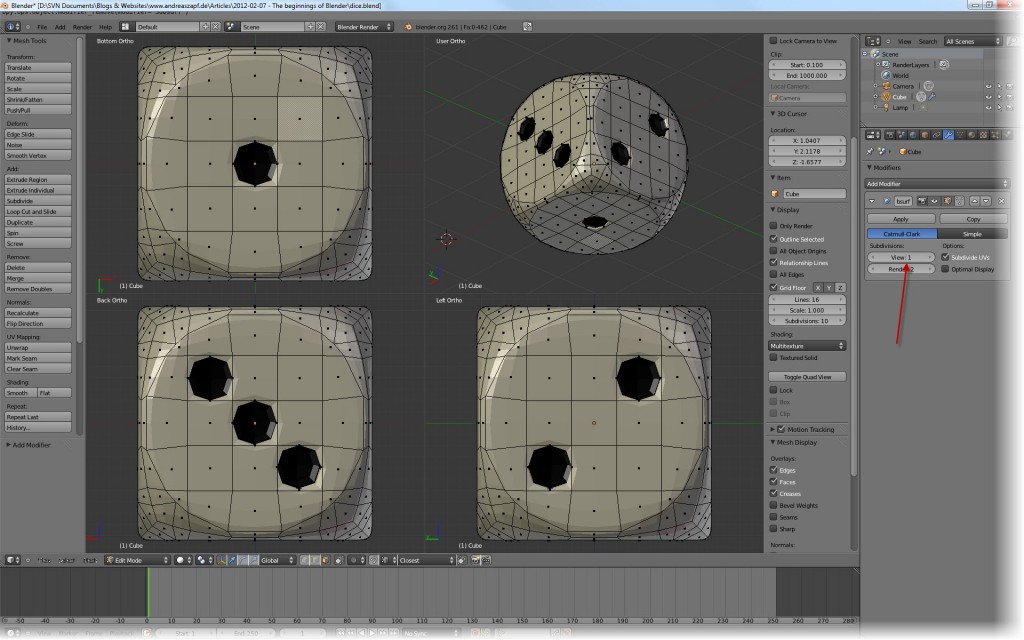 But we can do better – set the values for View and Render both to 3 – and we can be happy bunnies with out nice dice…
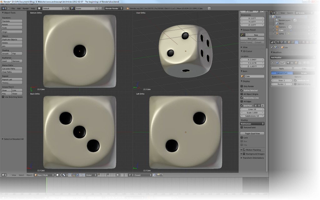 Now don’t forget to save all that hard work (better actually if you keep or develop a habit of frequently saving…) and we will look at the positioning of some lights, a base plate and the rendering one of these days…
Many thanks and my sincere respect to Berthold Lausch – once again – for without his video I would not have come along to write down my proceedings as a written tutorial…
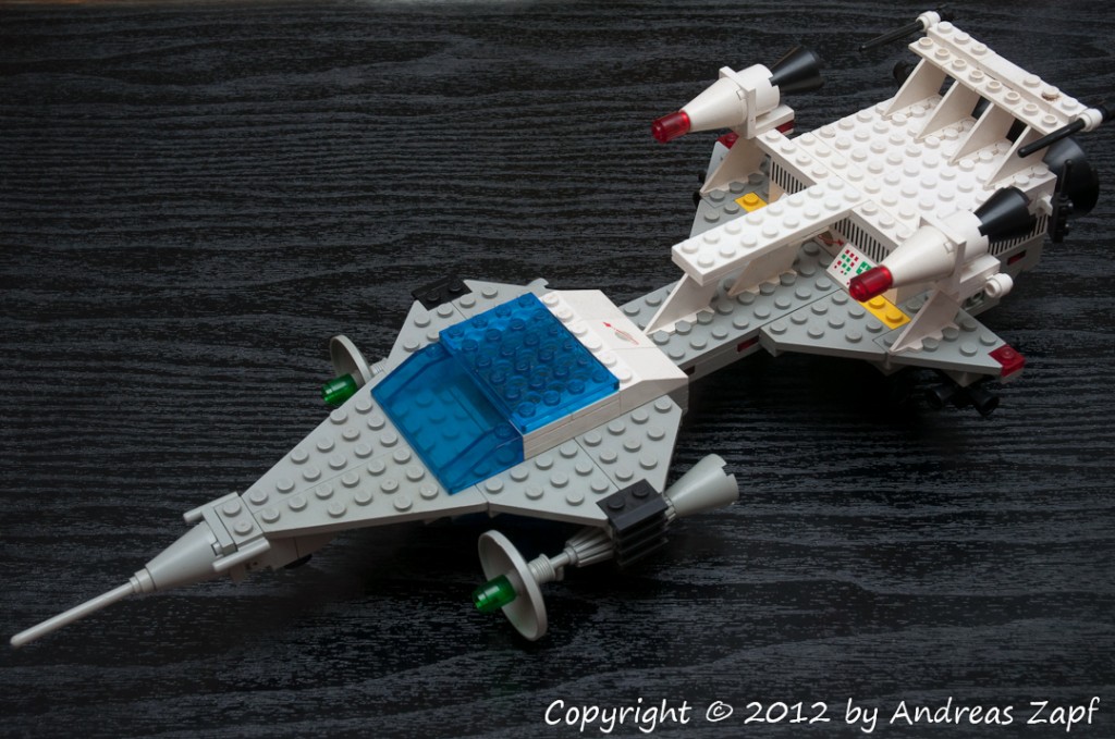
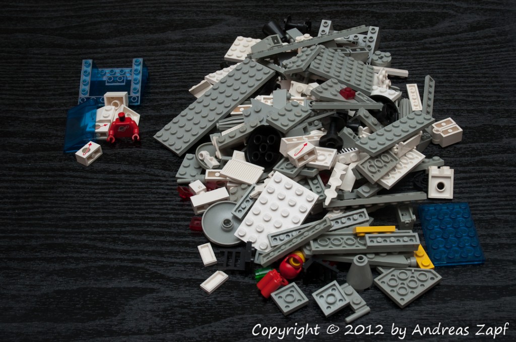
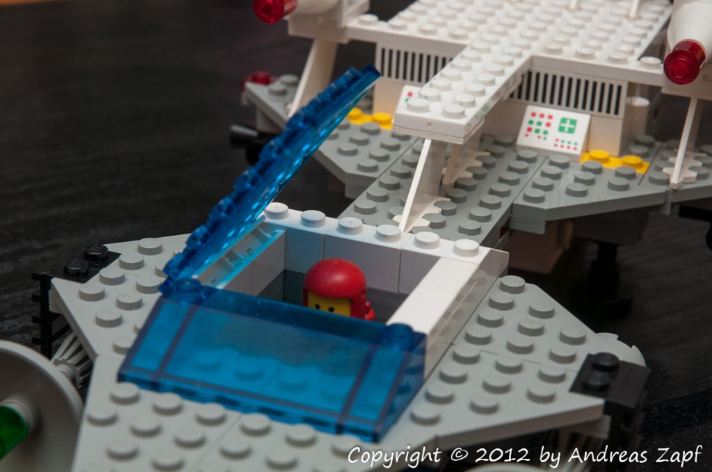
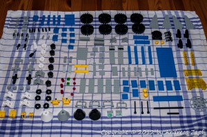 This one is a set I never owned before – so it is not in my original collection from the early 80’s but I did get it reasonably priced at eBay (again, I actually got two because the other one came in a set later).
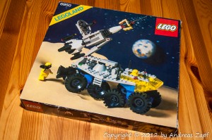 Unlike so many other sets that I own, this one comes with a specialty: the original box! Usually, when the box comes into play, prices soar at eBay but for one reason or the other, this did not happen for this particular auction.
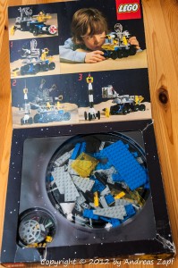 This kind of proofs my point that I favor the Classic Space Theme over any of the new space themes such as “Star Wars” or “Alien”: being made from really generic bricks and not following any fixed motive (such as a Star Destroyer) they tend to really encourage creativity. You can build whatever you can imagine – as long as you got the bricks to support it.
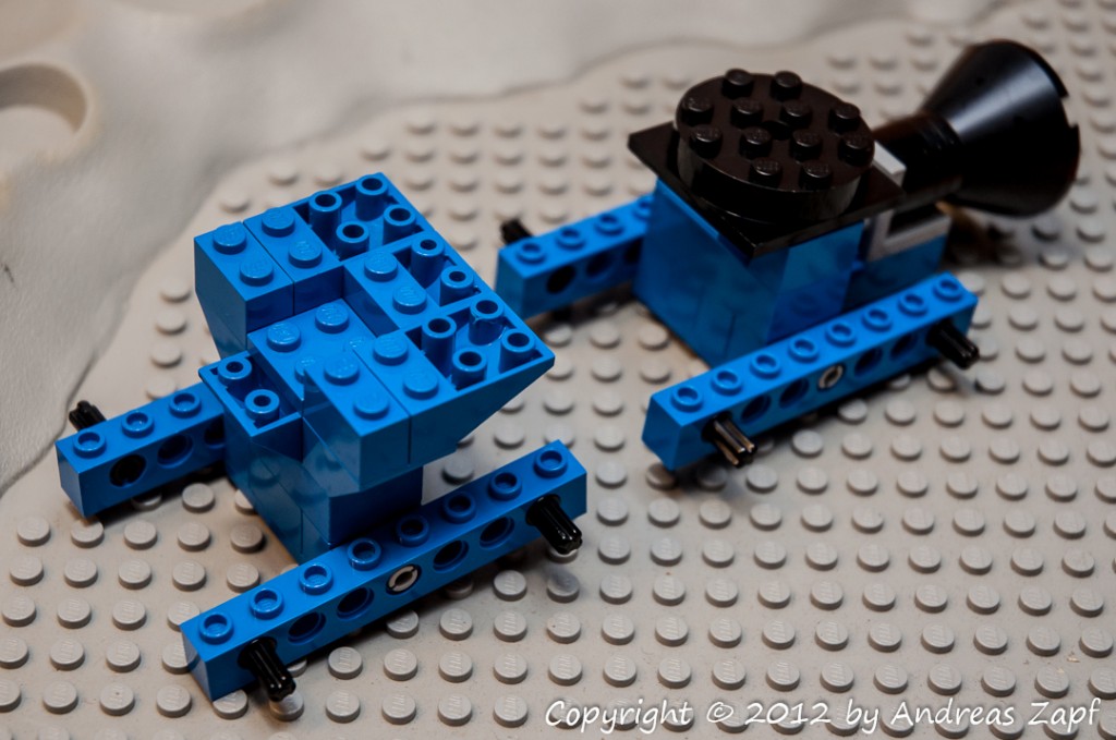 Above is a picture of the suspension section – front is left. As you can see, it will have eight large wheels mounted in pairs to four individually adjustable axles.In addition, the rear section in addition can be rotated to provide full maneuvering flexibility.
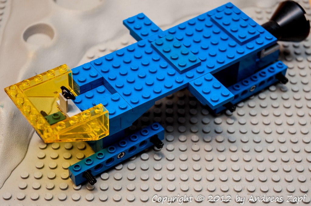 Both section are held in place by a large 6×14 plate which serves as the foundation of the platform itself. The front will also host the cockpit and (later) the control section.
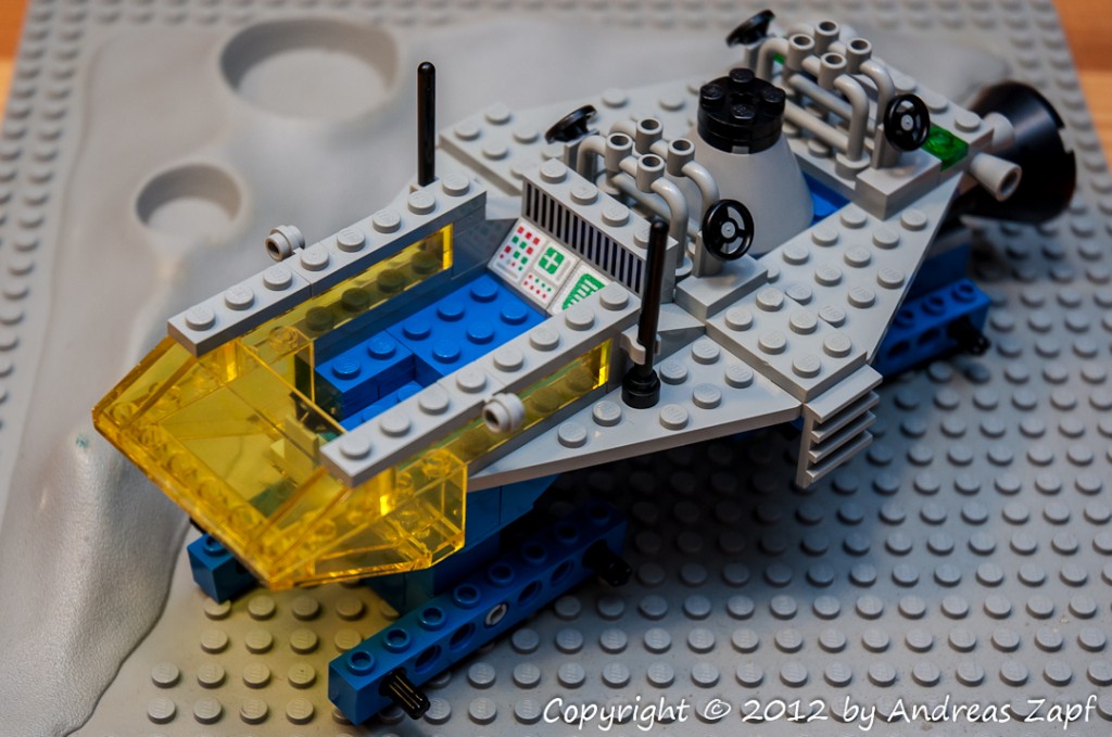 The platform itself is composed from four wing elements, access ladders, control thrusters and four steering wheels to control the crane, which will be mounted on the massive support structure seen above.
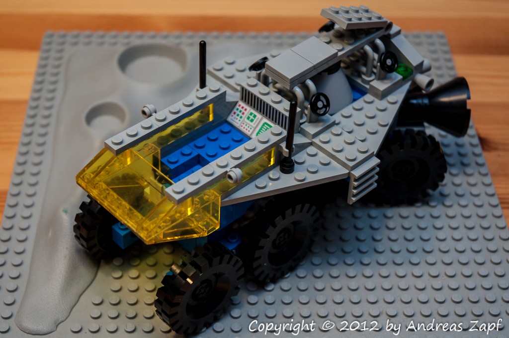 With the wheels mounted and the lower hinge in place, the Rocket Transport is almost finished. Another hinge and a small platform mounted on top of it will hold the rocket in place.
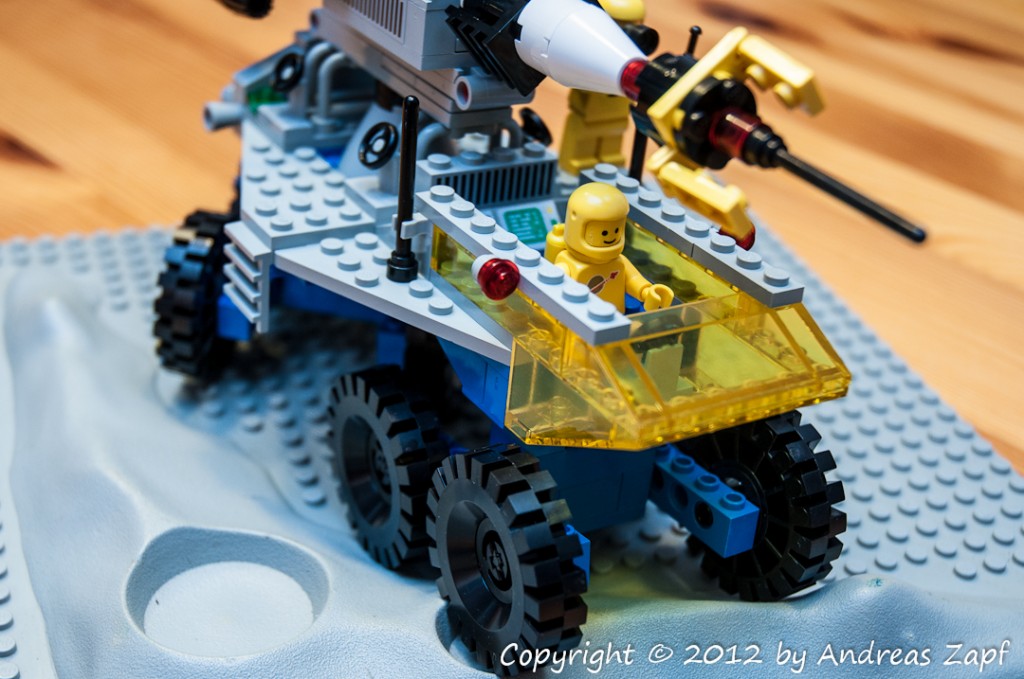
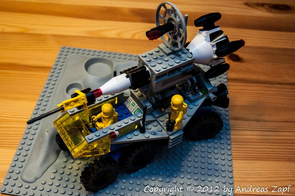 Fully assembled and placed on an original LEGO 306 Crater Plate, the dimensions and size of the model become apparent – here are some more close-up photos of the assembled model.
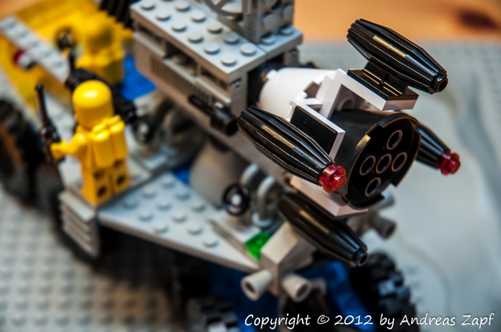
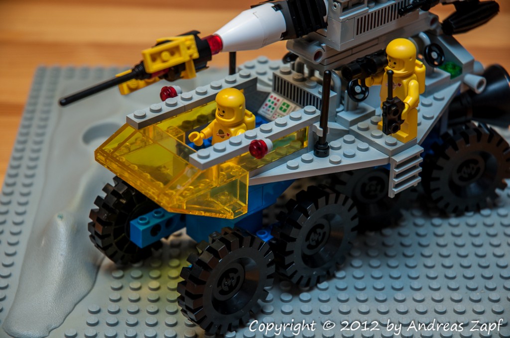 The Cockpit section above – and the aft section below. Note the rocket’s clever setup with the side thrusters – very nice model design.
 Finally, we can also see the hinges in action while the rocket is lifted into a launching position. The box stabilizing the rocket can be opened and the launch vehicle would simply drive forward to pull free.
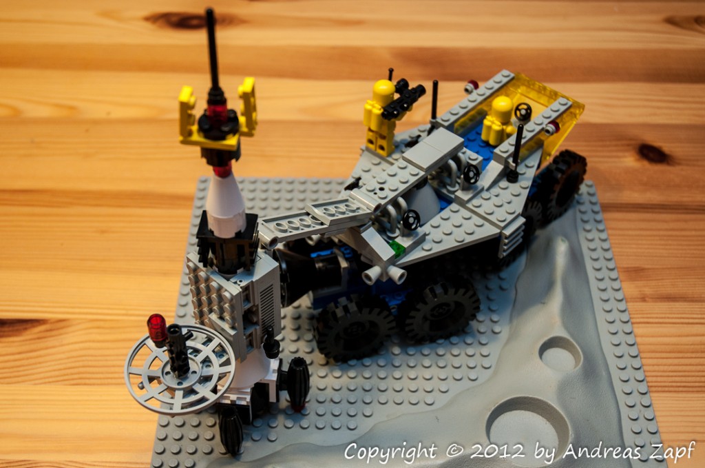 The final images shows the wheel suspension in action – the front right gear easily adapting to the terrain of the crater plate while the front left section remains level on the base plate.
